Some recent measurements, show me a 2-3 triodes phase inverter with less than 0.0x% distortion, with more than 50Vrms on both outputs, with no feedback 🙂
Attachments

I went looking for info on the transformer and the only thing I can find is an email address mentioned here. https://www.bartola.co.uk/valves/2016/07/31/dvb-in1166-input-transformer-test/#more-5668
I haven't advertised it yet, that's an old review for one of my input xfmrs, thanks for reminding me! 🙂
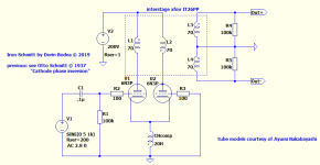
IT26PP is an evolution of IT26 presented here a couple of years ago:
https://www.diyaudio.com/community/threads/26-pre-amp.151421/post-7213064
IT26PP is an evolution of IT26 presented here a couple of years ago:
https://www.diyaudio.com/community/threads/26-pre-amp.151421/post-7213064
I have been using the almost exactly same topology for years, with a CCS in the tails. The low distortion is obviously due to the diff amp suppression of even harmonics. Might not be to everyone's liking.
@analog_sa - yes, but this is increasingly difficult for medium-mu tubes requiring higher impedance load, not any 4-windings xfmr will work there, same goes for the choke 🙂
Speaking of harmonics, is a lost battle trying to favor one or another, in my view the best approach is aiming for lowest, period
Speaking of harmonics, is a lost battle trying to favor one or another, in my view the best approach is aiming for lowest, period
Speaking of harmonics, is a lost battle trying to favor one or another, in my view the best approach is aiming for lowest, period
In full agreement here
Dorin Bodea
Very interesting!
Would you please take a measurement, and post a screen shot of a 5kHz or 10kHz square wave?
Thanks!
With those inductors in both the cathodes, and the plates, it looks similar to a Butler Oscillator.
I guess the 2 grid stopper resistors, and the two 100k secondary load resistors keeps the amplifier stable.
Many do not consider a direct connected pair of un-bypassed cathodes to be feedback, but it is negative feedback.
And yes, that kind of feedback does reduce the distortion of the stage.
Your implementation seems to work very well.
The 50Hz and 150Hz are perhaps from either the AC filament to cathode leakage [un-bypassed cathodes]; or from a power transformer magnetic field to the output transformer.
A magnetic field from a power transformer to the connected cathodes' choke, would cancel, as common mode interference cancels in a differential stage.
Any hum from full wave rectified B+ would be 100Hz; it would not be 50Hz and not be 150Hz. And, it would also be common mode, so it would tend to cancel as well.
Or, you might have a power mains & power grounds that causes a ground loop from the signal generator to the amplifier input.
Have Fun!
Last edited:
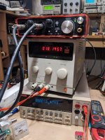
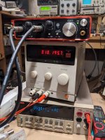
@6A3sUMMER - Thanks! I can do better than classic sqw, in attach. a ECC88/6N1P w/o any tweaking. I was talking about GNFB, not local feedback... however, with a slight modification, this circuit works also quite well with GNFB.
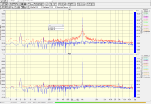
I didn't take any measures to better the results, as you can see the sound card sits on power supply which has a big mains transformer, therefore the spike at 50Hz. Also, the whole test is in the air without my usual shielding for xfmr...
In picture, math, M1=C1+C2, sum of both phases, taken with AD2 this time 🙂
Last edited:
Dorin Bodea
Very interesting!
Would you please take a measurement, and post a screen shot of a 5kHz or 10kHz square wave?
Thanks..
Copy that......If there is transformer coupling, there must be a leakage inductance spike. Can we see it ? That implies a response peak too.
The gremlin devil is in the detail.
Bench Baron
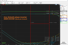
@benchbaron - what will be the purpose of that? This transformer is customized for this app... and you have the detailed bandwidth above. If you look for spikes there's one around 25kHz signaled by the level of THD too
... however, in terms of bandwidth, I can tell you that this xfmr performs better in SE driven by a triode 26 or in a PP to PP classic app.
... however, in terms of bandwidth, I can tell you that this xfmr performs better in SE driven by a triode 26 or in a PP to PP classic app.
The spectrum analysis you quote each output 2V rms which is a common interstage voltage; initially you mention 50+50V RMS and for the next test, do the spectrum analysis at 20Hz and let´s have a look at F2 or 2nd harmonic level. This will have quite a bearing on the LF sound quality if one isn´t using gnfb. I am also tempted to make things more difficult by lowering the output resistors from 100K to 47K and see the distortion results.
You may wonder why such a level, but directly to a power tube grid, these voltages are realistic.
These things always interest me..
Bench baron
You may wonder why such a level, but directly to a power tube grid, these voltages are realistic.
These things always interest me..
Bench baron
The spectrum analysis you quote each output 2V rms which is a common interstage voltage; initially you mention 50+50V RMS
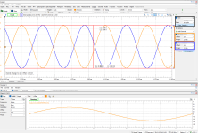
I'm sorry, you don't understand the graph; 2Vpk=~1.42Vrms is the input of the inverter and on output I have 40Vrms between phases
Max output from AD2 is 5Vpk=~3.57vRMS which gives ~100Vrms between phases, all of these from a common 6N1P picked randomly from a dusty old box 🙂 ... see the new graph for this case
Regarding transition from 100k to 47k nothing spectacular happens with THD and output level and yes, this circuit will hapily drive output tubes into AB2 class!
Last edited:
Looks pretty good to me.
I once used a pair of 6C45pi triodes to make a phase inverter.
A 5H choke (constant current source for the low impedance cathodes that worked pretty good; 6C45pi cathode to cathode negative feedback); and the plates drove a push pull interstage transformer (6C45pi plate to plate negative feedback). The interstage drove a pair of 300B in push pull.
Bench tested well, and sounded pretty good.
I had Jack Eliano's Electra Print Audio push pull interstage driver transformer; and a Lundahl push pull interstage transformer.
For the 6C45pi triodes and 5H choke, I used Jack's interstage.
Put current source to cathode instead of inductance and you get even better THD.
I have, no joy... 🙁
What kind of current source it was?
I'm playing with this idea starting 2018 or so (from time to time, I mean) and I've tried something with LM334 and something with a JFET... it was not an issue of THD mainly but something to deal with frequencies above (or around) 20kHz - choke acted better
I had playing with similar more than 10 years ago and with solid state current source and adjustable amplification balance (to compensate tube parts imbalances) I get THD less than 0,0x%. But not in very wide frequency range as tubes balance was different on different frequencies.
@kaameelis - exactly... on the other hand I'm striving to keep things simple and predictible, "vintage" if you like. Also, here intervenes playing with those profound contradictory requirements in the xfmr on an extended frequency range
Last edited:
- Home
- Amplifiers
- Tubes / Valves
- Iron Schmitt phase inverter - lowest THD seen