Hello all.
Bought this amp broken to try and expand my repairs and learn new amplifiers.
The power supply and output devices test as they should with my meter reading other posts, so dont think any are shorted.
The amp draws current at idle and increases as the xover module is inserted and increases more when a signal is applied even at 0 volume.
Nothing seems to be heating up, the RCA shield fuse is open, and the TP U5-6 has 10vdc on the pin. There is also 10vdc on the L+ bridging terminal.
I used the non bridging terminal negative for the ground reference with my meter.
I don't have a schematic any help would be appreciated.
Bridge the fuse with a 1 ohm resistor if you don't have a fuse.
Jump the module as is shown on the main kicker page of the tutorial:
repairnoteskicker.htm
There are partial diagrams on that page and the ZR1000 diagram in the Kicker folder will be similar.
Are the transistors clamped to the heatsink to prevent bias runaway?
Jump the module as is shown on the main kicker page of the tutorial:
repairnoteskicker.htm
There are partial diagrams on that page and the ZR1000 diagram in the Kicker folder will be similar.
Are the transistors clamped to the heatsink to prevent bias runaway?
Ok ill run a jumper for the fuse.
I no longer have the tutorial as I installed windows 10 and the copy I had was for windows 7.
I think I remeber seeing a photo of the outside pins of the socket bridged together?
I no longer have the tutorial as I installed windows 10 and the copy I had was for windows 7.
I think I remeber seeing a photo of the outside pins of the socket bridged together?
I replaced the fuse with a 1206 1 ohm resistor and powered the amp. The current draw subsided but reains at 2.5 amps, seems high.
The right channel produces clean audio, but the L+ bridging terminal still has the 10vdc in it as well as the test point U5-6. I remember seeing one of papazbill's posts saying there should be no more than 1 volt on this test pin.
The right channel produces clean audio, but the L+ bridging terminal still has the 10vdc in it as well as the test point U5-6. I remember seeing one of papazbill's posts saying there should be no more than 1 volt on this test pin.
Do you have any DC on the output pins of the op-amps near the RCA jacks?
Do you have the module jumped out and out of the amp?
Do you have the module jumped out and out of the amp?
There is no DC on the output pins of those 2 op-amps.
Post #4, if not wire what do you recommend?
Post #4, if not wire what do you recommend?
The fuse can't be a wire. The jumpers for the module are wires.
If you still don't have audio with the module bypassed, post the DCV on all terminals of the TL071 that you said had too much DCV.
If you still don't have audio with the module bypassed, post the DCV on all terminals of the TL071 that you said had too much DCV.
Post #5 I didnt use wire on the fuse, I replaced with a 1206 1 ohm smd resistor. I have audio on the right channel, have not checked for audio on the left due to the 10vdc on that channel.
I'll remove the module and jump the outer pins with wire.
I'll check the DCV on the TL071's.
I'll remove the module and jump the outer pins with wire.
I'll check the DCV on the TL071's.
After looking up a few data sheets, I found U5 to be defective.
I replaced U5 and the 10vdc is gone from the L+ bridging terminal.
Both channels bias and produce clean audio.
The crossover module is stuck in full range but I pulled one from a parts amp and all is good.
The 100k gain pots are scratchy so I ordered them from mouser.
The Mouser part number is 531-PT10MH-100k, the manufacturer part number is PT10MH01-2020.
U5 deals with DC offset. It can have excessive DC on it's output due to being defective or from something driving the output to have DC due to another failed part. Looking at the voltages on the IC will generally tell you which is the problem.
I've seen the caps on the modules fail (out of tolerance) and that caused oscillation and other problems.
I've seen the caps on the modules fail (out of tolerance) and that caused oscillation and other problems.
Ok now I know why you wanted the DCV readings from it. Due to the DCV being gone now that its replaced, and its reading the same as the other channel, I would say it was defective and DCV wasn't being driven to it by another problem.
I've seen them fail. I hate to tell anyone to replace anything without doing everything possible to ensure that it's defective.
I agree Perry.
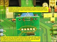
Just a final question, will the 1206 1ohm resistor I put in place of the RCA shield fuse be a suitable long term replacement?
Just a final question, will the 1206 1ohm resistor I put in place of the RCA shield fuse be a suitable long term replacement?
I don't think it will cause any problem and it should be enough to protect the head unit if the transformer has an intermittent short. While it's on the bench, twist/push/pull on the transformer to confirm that there is no intermittent short.
If the screw near the transformer reads 0 (1 ohm) ohms to the RCA shields, you need to use a nylon screw in that location as well as making sure that the plastic standoff is in place between the heatsink and the board. The same thing applies to the other mounting screw.
Isn't the fuse on top of the board in this amp?
If so, order the fuse and install it later.
- Home
- General Interest
- Car Audio
- Kicker ZR360 REV F