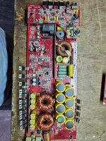
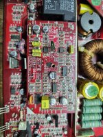
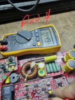
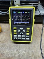
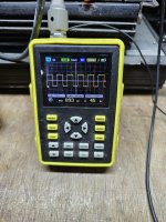
Good afternoon everyone, on this occasion I am urging you to repair this Kicker brand amplifier model ZX1000.1 REV 2.1. At the beginning, damage was found in the power supply, it has already been recovered and in the output stage there is an auxiliary supply that was damaged, the 2 htp18n06g were replaced and the 1n4002 diode is already oscillating, but now I have stopped at the driver card, I already managed to get it to turn on and stay on, I don't have any pulses in the output fets, I mention that I have the fets outside the board since if I leave them inside they won't stay on, greetings
Attachments

Someone who knows these amps better than I do will likely step in but we can check a few things.
Do you have all of the marked voltages on the driver board present and correct?
What signal do you see on pin 5 of U203.
Do you have all of the marked voltages on the driver board present and correct?
What signal do you see on pin 5 of U203.
Confirm that the ceramic capacitor connected to pin 3 is connected to ground on the driver board. If so, jump the capacitor with a wire (leg from a 1/8w resistor).
Does that give you drive pulses at the output of the LM361?
Does that give you drive pulses at the output of the LM361?
at the outputs of the LM361, pin 9 and 11? The capacitor is at pin 3 and ground and does not generate a signal at its outputs when placing the wire
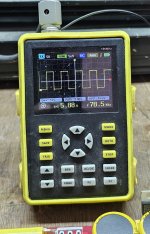
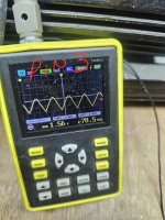
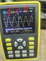
To clarify, you have a triangle wave on pin 4 and 0v DC on pin 3?
DCV on the two output terminals of the LM361?
DCV on the 4 PS terminals of the LM361?
DCV on the two output terminals of the LM361?
DCV on the 4 PS terminals of the LM361?
To clarify, you have a triangle wave on pin 4 and 0v DC on pin 3? Yes
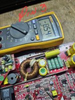
DCV on the two output terminals of the LM361? Pin 9. 4.64v Pin 11. 0v
DCV on the 4 PS terminals of the LM361?
Pin 1. 15.36v
Pin 6. -15.35v
Pin 14. 2.6 with reference to pin 10 and 4.9v with reference to gnd
DCV on the two output terminals of the LM361? Pin 9. 4.64v Pin 11. 0v
DCV on the 4 PS terminals of the LM361?
Pin 1. 15.36v
Pin 6. -15.35v
Pin 14. 2.6 with reference to pin 10 and 4.9v with reference to gnd

If 8, 13 and 14 are all 5v above pin 10, you have ±15v on the supply terminals 1 and 6 and the triangle waveform is constantly crossing the voltage on pin 3 (both read 0v DC), you should have a square wave output. If not, that would tend to indicate that the LM361 is defective.
Are you saying that pins 9 and 11 only connect to those diodes?
If the amp won't stay on with the outputs in the circuit, you won't be able to do any further troubleshooting.
Do you think the problem before could simply have been dirty contacts on the driver board connector?
If the amp won't stay on with the outputs in the circuit, you won't be able to do any further troubleshooting.
Do you think the problem before could simply have been dirty contacts on the driver board connector?
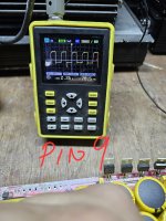
oh no, it first goes through a 1kohm resistor followed by another 2490 ohm resistor and touches some diodes until it reaches the lm319 and at the outputs of the lm319 I don't see it coming out and and I don't think it's because of dirt, I just pushed it all the way down.
Which terminals of the LM319 do you see square waves on?
Do you have supply voltage on the LM319 (DCV across pins 6 and 11)?
Do you have supply voltage on the LM319 (DCV across pins 6 and 11)?
- Home
- General Interest
- Car Audio
- Kicker ZX1000.1