Howdy gang!
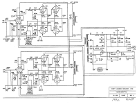
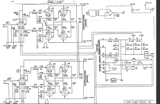
I've got a Cary SLA-30 from the early 90s. The schematic is barely readable (at least to me) and I'm trying to copy it all out into Kicad so that it's more usable, and also, so I can eventually tackle the rev 1 version that changes the bias, but I'd like to get how it's currently built (rev 0) drawn out properly.
My issue is simply trying to understand the original schematic because of how it's drawn, and re-drawing it in Kicad. If anyone could look at this and see if I'm making any terrible errors, or if anyone has any general commentary, that would be great!
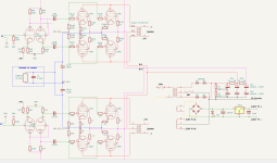
Here's the original, and the translation into Kicad that I'm working on.
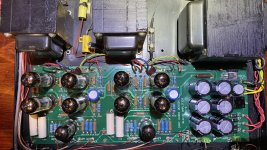
Edit: Added internal picture
I've got a Cary SLA-30 from the early 90s. The schematic is barely readable (at least to me) and I'm trying to copy it all out into Kicad so that it's more usable, and also, so I can eventually tackle the rev 1 version that changes the bias, but I'd like to get how it's currently built (rev 0) drawn out properly.
My issue is simply trying to understand the original schematic because of how it's drawn, and re-drawing it in Kicad. If anyone could look at this and see if I'm making any terrible errors, or if anyone has any general commentary, that would be great!
Here's the original, and the translation into Kicad that I'm working on.
Edit: Added internal picture
Attachments
Last edited:

LOL yeah, I noticed that. I forgot the 10k resistor in series with it, and I need to measure that cap, it has a ridiculous value because it just says 10 on the schematic, and it's a little orange drop cap that I have to measure.The errors I've seen are that you will blow up the LED and C8's value is 1 000 000 times too small.
Attachments
Is there no need for a fuse?After the bridg 500mfd capacitor..... so the charge impact is not low. you change frome 410 to 500 mfd.
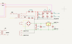
There's at least one serious error in the original.
R3 in the power supply is drawn twice and both are given as 5k / 2W.
This cannot be correct because the entire current for the output tubes would run through the 1st 5k which would burn almost the entire B1+ voltage.
Either the 1st R3 is a choke or doesn' t exist at all or something else ...
Check the actual hardware ...
There are two fuses on the unit that aren't indicated, one on the mains and one on the negative side of the bias loop where it says "mounted on chassis"Is there no need for a fuse?After the bridg 500mfd capacitor..... so the charge impact is not low. you change frome 410 to 500 mfd.
Also, the original mains caps got a little bump when I recapped it, the originals were 820, and the replacement snap ins that fit the board spacing were 1000.
Last edited:
This I will have to verify. I can tell you there is no choke, and the same number of resistors are countable on the board. I'll have to look the underside.This cannot be correct because the entire current for the output tubes would run through the 1st 5k which would burn almost the entire B1+ voltage.
DrDyna,
Thanks for sharing!
Interesting amplifier.
Parallel Pentode Push Pull
Not Shown: Negative feedback connection from one lead of the output transformer secondary; and ground of one secondary lead.
EL84s ?
Thanks for sharing!
Interesting amplifier.
Parallel Pentode Push Pull
Not Shown: Negative feedback connection from one lead of the output transformer secondary; and ground of one secondary lead.
EL84s ?
Yeah, it's supposed to have EL84s in it, but apparently the bias is pretty high and it was made when tubes were cheap, so to keep from going through them, Cary's suggestion was to replace them with 7189a tubes, which I did. There's 33-35mA on each tube as it sits.DrDyna,
Thanks for sharing!
Interesting amplifier.
Parallel Pentode Push Pull
No negative feedback
EL84s ?
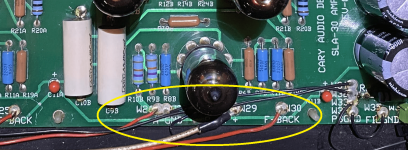
Also, there is feedback, R11 /22k sits on the cathode of the input 12ax7, and that wire runs over to the negative speaker terminal.
Edit: Attached pic of the input / feedback wiring, the 2 red wires go back to the speaker terminals.
Attachments
Last edited:
So this is the section that I have the most questions about, does this look accurate compared to the schematic? It's hard for me to tell because all the wires just kinda go over each other in the original schematic, did I do this right?
Note, the schematic makes it look like there's two "mounted on chassis" sections but they are shared in the amp.
Does this look like it produces fire or audio?
Note, the schematic makes it look like there's two "mounted on chassis" sections but they are shared in the amp.
Does this look like it produces fire or audio?
Attachments
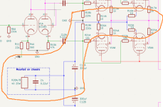
Original looks to me like there are two 150 Ohm 25 watt bias resistors (one for each channel) each is bypassed by a 330uF + .22uf so all 3 per side R+C+C in parallel tp ground from the junction of the current sense resistors on the individual cathodes.
I checked them, though they are both labelled R3 on the original schematic, on the board, R3 is 25 ohms and R4 is 1k.There's at least one serious error in the original.
R3 in the power supply is drawn twice and both are given as 5k / 2W.
This cannot be correct because the entire current for the output tubes would run through the 1st 5k which would burn almost the entire B1+ voltage.
Either the 1st R3 is a choke or doesn' t exist at all or something else ...
Check the actual hardware ...
Attachments
It's not wired like that in the amplifier though, so I updated it on the schematic that I'm trying to build.Original looks to me like there are two 150 Ohm 25 watt bias resistors (one for each channel) each is bypassed by a 330uF + .22uf so all 3 per side R+C+C in parallel tp ground from the junction of the current sense resistors on the individual cathodes.
If you look at the picture I posted of the inside of the amplifier, you can see how they did it. There's a red and black wire on the back of the board, labelled R+ and R- for each channel, however both of the R- wires and both of the R+ wires go to that big 25w 40 ohm resistor that's screwed down between the output transformers, and both of the R- wires go into that fuse holder, and then into the other side of that same resistor, that's also got that .22 Kimber capacitor in parallel with it.
The big blue high temp caps that sit next to the tubes are the 330uf.
^ Well one bias resistor works but is the fuse between the bias resistor and ground? That is not making sense to me.
The two spots on the board marked R- are wired to one side of the fuse, and then one wire goes from the other side of the fuse to the other side of the resistor and cap.Well one bias resistor works but is the fuse between the bias resistor and ground
So basically if the fuse goes, it opens everything in the "mounted on chassis" box.
Attachments
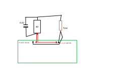
Based on that, I guess the cathode bias resistor finds ground through R- and the fuse between them seems like it could be a bad idea. Your drawing with the bottom going to ground sans fuse looks better to me. I'm not an expert but it seems to me that the cathode could charge up to some high voltage with the fuse open until you get leakage that lets the tubes run away and cook.
Yeah, it is a little odd the way they've built it.Based on that, I guess the cathode bias resistor finds ground through R- and the fuse between them seems like it could be a bad idea. Your drawing with the bottom going to ground sans fuse looks better to me
Part of the reason I've got so many questions about it, I would like to tackle the rev 1 update, which adds adjustability, but before I try to even start on that, I want to make sure I understand the original schema and what's going on.
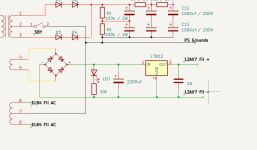
This is what's on the rev 1 schematic. In the top right, they show what seems to be an additional mains trafo, rectifier and potentiometer.
And nothing has any values, yay!
Attachments
Does anyone have an opinion about the rev 1 bias change? If I were to modify it like they're suggesting, what do you think the - voltage would have to be, since it's not mentioned? 20 or 30v I imagine? How much potentiometer, 10k? Should I also add a fixed resistor in case the wiper ever lifts?
Any and all comments / suggestions welcome. I'm normally pretty confident about electronics because if I pop something, it's usually a few dollars, but these tubes would cost me 400 to replace, lol.
Also, it looks like they've got the capacitor backwards in the additional power supply drawing, isn't it?
Last edited:
- Home
- Amplifiers
- Tubes / Valves
- Cary SLA-30 - Understanding schematics