So I want to make a valve audio preamp, but need a way to generate clean high voltage DC for the plates of my tubes. I started with rolling my own boost converter which worked well, but was unable to reach my desired voltage (about 200 V) as it was to much to ask from a single stage starting voltage of 12 V.
After some searching I came across this circuit which uses a step down transformer in reverse:

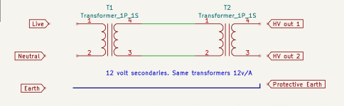
This looked nice and simple and began working on my schematic:

I added a MOSFET 'capacitance multiplier' as I want my supply to be as ripple free as possible, as well as the voltage climbing slowly will help in the following sections. C2 and C3 are probably over-kill but I have them in stock so may-swell.
The regulator is to power the filaments of two tubes and is tested and works great. My tubes only allow a 6.3 V connection.
So my first step down transformer is an enclosed 240 Vac primary, 12 Vac secondary, 36 VA. Picture here:

And my second 'step up' (backwards) transformer:

I have tested the low voltage side and regulator circuit, which seems to work perfectly.
I need about 220 V that supports a current draw of 20-30 mA.
My first question is are these transformers ideal for the application? giving that Transformer 1 gives about 13.5 Vac loaded with 1amp. how much can I expect on the high voltage side?
I plan to use large 470 uF 450 V capacitors (C2, C3) overkill I know. Is inrush current a concern on the coils?
I'm guessing the 0.01uf capacitors in parallel with the bridge rectifier diodes are to suppress EMF and high frequencies. Are these worth including?
For grounding, I plan to connect the grounds of the high voltage and low voltage side together and connect to the chassis that prevents the chassis becoming live. Is this the right approach?
I know this is a few questions rolled into one, but as my first high voltage project I want to make sure I get everything right. Thank you!
After some searching I came across this circuit which uses a step down transformer in reverse:
This looked nice and simple and began working on my schematic:
I added a MOSFET 'capacitance multiplier' as I want my supply to be as ripple free as possible, as well as the voltage climbing slowly will help in the following sections. C2 and C3 are probably over-kill but I have them in stock so may-swell.
The regulator is to power the filaments of two tubes and is tested and works great. My tubes only allow a 6.3 V connection.
So my first step down transformer is an enclosed 240 Vac primary, 12 Vac secondary, 36 VA. Picture here:
And my second 'step up' (backwards) transformer:
I have tested the low voltage side and regulator circuit, which seems to work perfectly.
I need about 220 V that supports a current draw of 20-30 mA.
My first question is are these transformers ideal for the application? giving that Transformer 1 gives about 13.5 Vac loaded with 1amp. how much can I expect on the high voltage side?
I plan to use large 470 uF 450 V capacitors (C2, C3) overkill I know. Is inrush current a concern on the coils?
I'm guessing the 0.01uf capacitors in parallel with the bridge rectifier diodes are to suppress EMF and high frequencies. Are these worth including?
For grounding, I plan to connect the grounds of the high voltage and low voltage side together and connect to the chassis that prevents the chassis becoming live. Is this the right approach?
I know this is a few questions rolled into one, but as my first high voltage project I want to make sure I get everything right. Thank you!
The regulation will be very poor. Don't use a wall wart!
Use a conventional correctly rated mains transformer and place the same size primary to primary.
DO NOT use 470u capacitors, they will stress the transformers too much.
47uF is adequate.
Don't bother with 10n caps, waste of time with modern 1N4007s.Connect the load side as you would do with a conventional circuit. Let the low voltage side float.
Transposed numbering shown in first drawing. Second drawing is more clear.
Attachments

Last edited:

Thanks, regulation is not 'to' important, as long as I can get 180v minimum @ 30ma.
so do you mean secondary to secondary (240vac > 12vac > 12vac > 200vac) ? and to use a completely different transformer for the filaments supply's?
47uF to replace C2 and C3 seem to result in over 1v ripple before the MOSFET, seems a little high. how would I calculate for a safe higher value capacitor?
Even if you use -relatively- low primary DCR 240:12 40-80W transformers back_to_back, the loss will significant, so HV AC voltage fell short of expectations.
Probably using 120-150W transformers is better solution.... but worth it?

Probably using 120-150W transformers is better solution.... but worth it?
For my Akido, I used a small toridal 240v in, 115-0-115 out, full wave rectified and regulated to 217v and a separate 6-0-6v toroid for the heaters, also regulated to 12v,
I abhor switched mode psus for audio applications though I did initially used a filtered 12v DC one for the heaters.
I abhor switched mode psus for audio applications though I did initially used a filtered 12v DC one for the heaters.
hmmm well how much could I expect from my transformer setup above? or is it easier to set it up and check? my seconded 'step up' transformer is rated 18va (9va x 2) and say i'm pulling 240v x 0.03a = 7.2w. less than half the rating 🤔 i know there will be less that 240vdc but im ok with 180v minimum.
The rule of the thumb: if you want not overheated transformer, must to use -at least- double power rating PT, than calculated primary power.
The stressing mainly depends of secondary current form. Large charging pulses (larger first capacitor) causes greater load.
The stressing mainly depends of secondary current form. Large charging pulses (larger first capacitor) causes greater load.
kinda wishing i put more work into my boost converter circuit design now :/ some will say its sacrilege though 😛
I could maybe try something like this:

LINK: https://sound-au.com/project238.htm
Driving a square wave into a mains transformer seems a bad idea for noise and EMF interference. But maybe a higher frequency sine wave instead? this would also be easier to filter. not sure about coupling capacitor C2 either 😕
It would basically be a Function generator > amplifier ab output stage > transformer
Hi mr_zener
I would certainty design and build something similar to your posted design and expect good performance.
As euro21 pointed out the small 9VA EI transformer may not be good enough, a small toroidal transformer (>=15VA) will be more suited to the task and will give less trouble with hum (B field). It looks like you tested it in a spice package, how did it work out? Using schottky rectifiers you may be able to make a 12.6VDC heater supply saving a few watts.
I have personally used wall wart type 12VAC out transformers to power valve equipment in the past using power transformers in reverse to generate B+. Silicon Chip magazine have used back to back toroidal transformers in some of their tube amplifiers.
I recently purchased a garden lighting transformer 240VAC input, 72VA, 12VAC output, it is IP68, double insulated and complies with all Australian standards. I intend to make some valve equipment that plugs into its nice 12VAC output socket. The current trend is a move towards switching power supplies, so I guess these garden transformers will become obsolete soon. HF noise can be a problem with switching supplies, the efficiency can be high and the life expectancy is somewhat dependent on the amount spent. I expect to make quite a few valve devices that will plug into this 72VA transformer. Jaycar Australia still sells 150VA and 105VA 12VAC garden lighting transformers. In Australia a 1A 12AC out wall wart costs almost as much as a 105VA garden lighting transformer!
Bridge rectifier capacitor type power supplies are a bit harder on transformers than resistive loads, quite a good idea is to measure the temperature rise in the transformer winding. When the transformer is cold the measure its DC resistance and again when it is hot, use the change in resistance to calculate the winding temperature.
I have a number of 200VA 240VAC to 24VAC toroidal transformers and have used them back to back in the past.
Transformer size versus pricing can be very interesting RS 173-0127 $28 AUD for 7VA or RS 671-8959 for 50VA.
Good luck with the project.
I see you just made another post, I was referring to the schematic in post #1.
This link might be handy. https://vertexcc.files.wordpress.com/2016/05/resistance-method-explained1.pdf
Last edited:
Thank you Tubekwk
my second transformer is a 12vac center tapped, so is that not 9VA * 2 if I ignore the center tap?
and my current draw is 30ma B+
As for the heater supply I only have 6.3V connections available on my 6N2P tubes, going from 12V to 6.3V at about 700ma (2 tubes) will be less than 5w of heat dissipation from the regulator. not ideal but I'm no stranger to heat sinks 😛
What do you think to the above idea and running the transformer at a higher frequency?
Last edited:
Q / What do you think to the above idea and running the transformer at a higher frequency?
A/ Been there done that. Depending on the transformer it can work very well, a winding designed for 10VAC at 50 Hz may work well with less loss at 20VAC 200Hz enabling more power through a given core, my experience has been torroidals seen to work efficiently to a higher frequency than EI cores, a good indication is lamination thickness on EI cores. Most 50Hz transformers work better with some increase in frequency. For vintage radio battery B+ supplies I normally run the 50Hz cores at around 100Hz, I have even pushed the frequency high so the leakage inductance drops the B+ voltage. Some sorm of slew rate limiting in the power FET's helps with RFI, this can be a simple as a larger gate resistance.
I have tested on the bench running a 240VAC to 12VAC transformer feeding with 24VAC for 480VAC out at a couple hundred Hz but have never used in in a design as yet but may well do at some time. Some sort of dead time is handy for the FET drive.
Maybe an SG3525 would be OK as a driver millions of these chips have been used so they have stood the test of time. They may only go down to 100Hz. There may be a spice model of it about somewhere.
https://www.onsemi.com/pdf/datasheet/sg3525a-d.pdf
I found this, not certain how good it is.
https://solderingmind.com/sg3525-inverter-circuit/
https://www.onsemi.com/pdf/datasheet/sg3525a-d.pdf
I found this, not certain how good it is.
https://solderingmind.com/sg3525-inverter-circuit/
So you driving a mains transformer with a square wave signal?
this does look good (from datasheet):

or:

I'd have to look into it some more, I only have a little experience with switching boost/bucks.
Basically just build a switching inverter? I would of thought filtering noise would be a problem, even at a higher frequency.
seems those FETS would be under a lot of load if its throwing one side to the other.
this does look good (from datasheet):
or:
I'd have to look into it some more, I only have a little experience with switching boost/bucks.
Basically just build a switching inverter? I would of thought filtering noise would be a problem, even at a higher frequency.
seems those FETS would be under a lot of load if its throwing one side to the other.
Yes I have driven mains transformers with a square wave always at a slightly higher than the transformers specified frequency and with some slew limiting. If properly designed the FET's will have no problem.
I would not suggest this topology for a tube preamp unless you want it as battery powered device as filtering noise can be an issue, your original 12VAC 50Hz transformer backward design will be the easiest to make work well.
If I was to make a high powered 12 or 24 volt DC powered tube amp I would probably use a toroidal mains transformer wired backwards with frequency and voltages scaled to suit as it is too much effort for me to wind a custom HF transformer.
Spice a few times build once 🙂
Seems if we are going down this road may as well go for a ZVS design with a flyback..
I'm thinking for my first high voltage project just keeping things simple, maybe start upping AC into my small transformer with a load and monitor current draw and temperature? obviously output voltage as-well.
I'm thinking for my first high voltage project just keeping things simple, maybe start upping AC into my small transformer with a load and monitor current draw and temperature? obviously output voltage as-well.
As I had not tested the 72VA 240V to 12V garden lighting transformer so I wired it to a cheap 15VA transformer with a multi tapped 1A secondary, the 12.5V tap was selected as the input, the 240V primary was wired to a bridge, a 47uF and a 5600 15W WW resistor, the output voltage was 272VDC as measured on a measured on a Fluke DMM. So 13.3 watts at 48mA.
So given satisfactory components the idea will work. If a linear voltage regulator is used the input capacitor value can be reduced so just enough headroom on low mains.
If a 20 watt toroidal core was used it is easy to place a few extra turns to buck or boost the output.
The open circuit voltage of the garden lighting transformer is 14.25VAC so I guess 12VAC with a 72 watt resistive load (halogen lamps).
When testing inverters I had just repaired, I used a 415vac to 240vac isolation transformer in reverse, powered from a variac, so I could run it on the bench.
I needed 540vdc bus voltage to power it up, and I ran a 180va induction motor, using a 250va transformer, without any overheating.
Transformer secondaries have additional turns to meet the full-load voltage specifications, so when used in reverse, the output voltage will be lower than that written on the label, but the bigger it is, the closer it will be.
Transformers don't care which is the primary and which is the secondary, but they don't like being overloaded.
IMHO the most safe solution for HV newbies to use appropriate PT with HV and filament coils.
For example TME sells satisfactory transformers in UK too.
https://www.tme.eu/gb/details/tsl40_001/transformers-with-fastening/indel/tsl-40-001/
I used these (and larger -100VA- TSL-100 too).
For example TME sells satisfactory transformers in UK too.
https://www.tme.eu/gb/details/tsl40_001/transformers-with-fastening/indel/tsl-40-001/
I used these (and larger -100VA- TSL-100 too).
To quote myself:how much could I expect from my transformer setup above?
the first transformer must supply the magnetising power, thereby reducing its remaining ‘useful’ VA. As a rule of thumb, subtract 5VA from the first transformer’s rating; whatever remains can be divided up between heater and HT power as required.
Let's round it off and say you have about 30VA available from the first transformer.
If you want 200Vdc at 30mA that's 6 watts, or about 9VA accounting for rectification, exactly what your second transformer is rated for. You should end up with 200-210Vdc in practice at that load.
That leaves 21VA for heaters, or about 12 watts in practice (low voltage rectification is less efficienct), so I'd estimate 700 to 800mA dc. It might be a bit of a stretch to get the full 1A unless you relax your HT to maybe 20mAdc.
Last edited:
- Home
- Amplifiers
- Tubes / Valves
- Step down transformer in reverse - safety and performance