Hi everyone, I want to share and hopefully get some inputs/feedback on my first two-way design. Please feel free to give any notes/pointers on what I missed.
Background
I've been lurking this forum for years and has been fascinated by the design work of all the people here but never pulled the trigger on doing a build.
And now it's the start of a new year, I decided it's time to try and do a project.
I've set a few priorities for this project:
Driver Selection
As for the drivers, the main considerations are availability and cost. Due to the fact that I live in the country where SB Acoustics are manufactured, it is pretty easy to get an SBA Driver.
I've been reading other people's designs with SBA drivers and I've read a couple of times that their published specs are close to real measurements, which is good for my non-measurement approach. Considering the low-cost target, I've went with their entry level 4 inch PFC series SB12PFCR25-4 and SB19ST-C000-4.
I use VITUIXCAD for every step in this design phase
1. Enclosure Design
I've inputted the parameters on the Enclosure Tool and come up with the tuning below, then I exported the SPL and Impedance

2. Baffle Dimensions
For aesthetic purposes, I try to get close to 1:1.62 for the dimensions, and considering the driver frames, I've came up with below design

3. Taking out IEC Baffle from Manufacturer Traced SPL
I would not go into details, but basically I followed the "design without measurement" guide on the stickied thread.
In summary:
4. Simulate On-Baffle Responses
For the tweeters, I used the diffraction tool with the baffle dimensions above with a 1000mm mic distance on-axis, import the half-space response, and export the 4-pi response with simulated off-axis responses. (which is very not ideal from what I understand, since there will be a lot of uncertainties occuring in the off-axis, due to dome design, etc, CMIIW)
For the woofers, there are a few more steps I did:
Using the merger tool, I imported the exported SPL response from enclosure tool and set the raw diffraction response from Diffraction tool as the LF part.
The HF part is the exported full-space woofer response (with the traced SPL) from the diffraction tool.
Then exported the merged response

4. Main Software Page
On the main software page, I imported the following as my drivers:
Woofer
SPL - Exported from Merger Tool
Impedance - Exported from Enclosure Tool
Tweeter
SPL - Exported from Diffraction Tool (full-space on-baffle response)
Impedance - Traced Manufacturer Graph
I set 17mm as the z depth of the woofer (I've seen this number on another person's project while lurking, but can't seem to find the exact page. I believe it was acquired through the late Jeff Bagby's technique to find acoustic offset), and -105mm as the y offset.
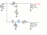
5. Crossover Design
The impedance peak of tweeter is at 1khz, and the woofer's response started to become messy around 4khz, so I decided to aim 2-2.5 khz as the crossover point.
After trying out and messing around, here is what I came up with.


6. CONCLUSION
Now what is remaining from me is to get any feedback from the forum, is there any steps I might have missed? Or if you have any input to the crossover design, what you would have changed, please let me know, I'm all ears for any improvements.
I'm planning to start the build in 2-3 weeks time so I still have time to make corrections and any changes.
And yes, after building the speaker, it is the plan to buy a measurement mic (I'm thinking UMIK-1) to conduct a proper measurement and validation of the design, and maybe design a new crossover using measured data.
Thank you, and looking forward to your feedbacks on this.
Background
I've been lurking this forum for years and has been fascinated by the design work of all the people here but never pulled the trigger on doing a build.
And now it's the start of a new year, I decided it's time to try and do a project.
I've set a few priorities for this project:
- 2-way design - I looked at this project as a learning experience and I think that I would miss out on the crossover design aspect if I were to do a full-range (which I believe is a very good choice for a first build for most people)
- Ported enclosure - similar to 1st point.
- Low cost - Since this is a first project, I don't want to spend big, but I also don't want it to be a very low quality build.
Driver Selection
As for the drivers, the main considerations are availability and cost. Due to the fact that I live in the country where SB Acoustics are manufactured, it is pretty easy to get an SBA Driver.
I've been reading other people's designs with SBA drivers and I've read a couple of times that their published specs are close to real measurements, which is good for my non-measurement approach. Considering the low-cost target, I've went with their entry level 4 inch PFC series SB12PFCR25-4 and SB19ST-C000-4.
I use VITUIXCAD for every step in this design phase
1. Enclosure Design
I've inputted the parameters on the Enclosure Tool and come up with the tuning below, then I exported the SPL and Impedance
2. Baffle Dimensions
For aesthetic purposes, I try to get close to 1:1.62 for the dimensions, and considering the driver frames, I've came up with below design
3. Taking out IEC Baffle from Manufacturer Traced SPL
I would not go into details, but basically I followed the "design without measurement" guide on the stickied thread.
In summary:
- Trace Woofer Manufacturer data using "SPL Trace"
- Model an IEC Baffle diffraction response using "Diffraction" tool (Important note: SBA data is from 31.6 cm mic distance)
- Take out IEC Baffle from traced SPL using "calculator"
- Do the same for tweeter
4. Simulate On-Baffle Responses
For the tweeters, I used the diffraction tool with the baffle dimensions above with a 1000mm mic distance on-axis, import the half-space response, and export the 4-pi response with simulated off-axis responses. (which is very not ideal from what I understand, since there will be a lot of uncertainties occuring in the off-axis, due to dome design, etc, CMIIW)
For the woofers, there are a few more steps I did:
- I modeled the baffle and driver location according to drawing above, with the same settings as the tweeter (1000mm, on woofer's axis)
- I exported out the raw diffraction/bafflestep response
- Import the half-space response of the woofer
- Export the full-space simulated response.
Using the merger tool, I imported the exported SPL response from enclosure tool and set the raw diffraction response from Diffraction tool as the LF part.
The HF part is the exported full-space woofer response (with the traced SPL) from the diffraction tool.
Then exported the merged response
4. Main Software Page
On the main software page, I imported the following as my drivers:
Woofer
SPL - Exported from Merger Tool
Impedance - Exported from Enclosure Tool
Tweeter
SPL - Exported from Diffraction Tool (full-space on-baffle response)
Impedance - Traced Manufacturer Graph
I set 17mm as the z depth of the woofer (I've seen this number on another person's project while lurking, but can't seem to find the exact page. I believe it was acquired through the late Jeff Bagby's technique to find acoustic offset), and -105mm as the y offset.
5. Crossover Design
The impedance peak of tweeter is at 1khz, and the woofer's response started to become messy around 4khz, so I decided to aim 2-2.5 khz as the crossover point.
After trying out and messing around, here is what I came up with.
6. CONCLUSION
Now what is remaining from me is to get any feedback from the forum, is there any steps I might have missed? Or if you have any input to the crossover design, what you would have changed, please let me know, I'm all ears for any improvements.
I'm planning to start the build in 2-3 weeks time so I still have time to make corrections and any changes.
And yes, after building the speaker, it is the plan to buy a measurement mic (I'm thinking UMIK-1) to conduct a proper measurement and validation of the design, and maybe design a new crossover using measured data.
Thank you, and looking forward to your feedbacks on this.
Attachments

No comments on your design as I don't have the expertise, but here's a link to a commercial kit (Oz) which uses the same tweeter and the 8 ohm version of the SB12. Due to its commercial/IP status, crossover details are of course not available:
http://www.theloudspeakerkit.com/lsk-m4s-mini-monitor-kit
Geoff
http://www.theloudspeakerkit.com/lsk-m4s-mini-monitor-kit
Geoff
Not really qualified to critique the design per se, but from long experience I question you're wanting to emphasize the ~ 1 - 1.25 kHz BW even a little bit where 'whack'/tinny' resides.
In my experience such small baffles produce rather omnipresent baffle step behavior, much more (easily more than +5dB with sharp rise ‘on the step’) than your sim shows. So I doubt your analysis is spot on. The lowpass crossover values also don’t match what in my experience is usual.
Dibirama measurements are quite different from the responses/values of the SBA datasheet.
https://www.dibirama.altervista.org...s-sb12pfc25-4-mid-woofer-4-4-ohm-60-wmax.html
https://www.dibirama.altervista.org...s-sb12pfc25-4-mid-woofer-4-4-ohm-60-wmax.html
Conclusion?…..not good
You’re crossing far too early for both drivers……….3.5k is the ballpark you wanna be in with a 19mm dome. Not sure what ‘mess’ you’re referring to with the SB12……it’s smooth out to 8k. You want to look at the off axis response here and use the sb19’s very wide dispersion to your advantage.
Remove the faceplate of the SB19 and notch it for the flange of the SB12 to get your C2C spacing as close as possible. This will tilt your forward lobe down and the listening axis will be on the midwoofer.
Stand alone, this is a nearfield speaker for all your efforts at the highest fidelity. Placed on stands out in a room with a central subwoofer though, this will image like crazy and be a lot of fun.
Enjoy the process.
Thank you for the feedbacks,


I don't know if this has any correlation, but the downward slope is similar to the response I got if using the extended z model in the enclosure tool (and checking the "show effect of inductance")

Regarding the mess in SB12, I'm basically referring to the manu published response where it starts to have significant peaks and dips.
Good idea on messing with the SB19 flange but I think I don't want to do that now, but I'll remember that once I get to tweaking some more in the future.

I'm really taking this the wrong way, but seeing the visible crossover parts count (2 resistor, 2 inductors, 3 caps) is the same is somewhat encouraging 😊😂.No comments on your design as I don't have the expertise, but here's a link to a commercial kit (Oz) which uses the same tweeter and the 8 ohm version of the SB12. Due to its commercial/IP status, crossover details are of course not available:
http://www.theloudspeakerkit.com/lsk-m4s-mini-monitor-kit
Geoff
Thanks GM for the input, I'll try to tweak things some more, from what I can see I think it is caused by the resonance response of the tweeter at 1k, but I'm still avoiding a notch filter for the time being, hopefully I can cover those points with tweaking the slope filters.Not really qualified to critique the design per se, but from long experience I question you're wanting to emphasize the ~ 1 - 1.25 kHz BW even a little bit where 'whack'/tinny' resides.
Well this is the baffle response from the diffraction tool for the woofer, and I try to account for this in the lowpass, which is shown by the sloping response from 250hz in the filter tabIn my experience such small baffles produce rather omnipresent baffle step behavior, much more (easily more than +5dB with sharp rise ‘on the step’) than your sim shows. So I doubt your analysis is spot on. The lowpass crossover values also don’t match what in my experience is usual.
Thank you for the info, well this is indeed quite different.Dibirama measurements are quite different from the responses/values of the SBA datasheet.
https://www.dibirama.altervista.org...s-sb12pfc25-4-mid-woofer-4-4-ohm-60-wmax.html
I don't know if this has any correlation, but the downward slope is similar to the response I got if using the extended z model in the enclosure tool (and checking the "show effect of inductance")
Thank you, I'll try to tweak some more once I have the time and I'll try crossing higher.Conclusion?…..not good
You’re crossing far too early for both drivers……….3.5k is the ballpark you wanna be in with a 19mm dome. Not sure what ‘mess’ you’re referring to with the SB12……it’s smooth out to 8k. You want to look at the off axis response here and use the sb19’s very wide dispersion to your advantage.
Remove the faceplate of the SB19 and notch it for the flange of the SB12 to get your C2C spacing as close as possible. This will tilt your forward lobe down and the listening axis will be on the midwoofer.
Stand alone, this is a nearfield speaker for all your efforts at the highest fidelity. Placed on stands out in a room with a central subwoofer though, this will image like crazy and be a lot of fun.
Enjoy the process.
Regarding the mess in SB12, I'm basically referring to the manu published response where it starts to have significant peaks and dips.
Good idea on messing with the SB19 flange but I think I don't want to do that now, but I'll remember that once I get to tweaking some more in the future.
Change your z offset on the woofer to zero. Change the y offset on the tweeter to zero and make it negative 105 mm on the woofer.
Try a tuned series LCR in parallel to the woofer after the lowpass section. Thus you can ‘notch out’ the bump. Take 1mH, 15uF and 10R for starters, change L up and C down for finetuning.Well this is the baffle response from the diffraction tool for the woofer, and I try to account for this in the lowpass, which is shown by the sloping response from 250hz in the filter tab
View attachment 1269865
Apparently the version on the Italian website was a preliminary and the FR measured is coincident with the preliminary datasheet of SBA.Thank you for the info, well this is indeed quite different.
Also my previous comment was not on spot because you are using the pfcr (round flange). Well they say that only the basket shape is different... so in the end it's always better to do your own measurements on an actual baffle.
I agree with xo frequency >/= 3KHz
In Diffraction tool, the distance for the low frequency part should be at least 3m (see Kimmo's guide on vcad2 website).
In Merger tool, check the option "Force to Gradient".
Enjoy your build
I've played around a bit, and made changes to the z offset setting as advised by 4eaudio above to set woofer z to 0 and this is what I came up with (4khz xo point)

Just to make sure, is setting the driver z offset not a recommended practice when no measurement is used? I basically found some typical driver offsets on the web as my "17mm" reference.
And a question, I have a cheap mic and an audio interface which I know is not suitable for crossover design.
But for the purpose of z-offset calculation using Jeff Bagby's method, do you think it's enough?
In my mind, it should be somewhat suitable since all measurements needed (tweeter, woofer, combined) in the method is measured with the same mic.
The SB12 will be beaming a little at 4khz but everything is a compromise to a degree...........i don't see the 4k crossover being an issue other than narrowing the vertical listening window a little.
Google search for designs using the SB19ST
I found a claim that Dennis Murphy used those in his latest mini monitors crossed at 2100Hz but the link was dead.
Ron_E won crossed them at 2800hz in a speaker that many people praised.
This is just from a quick Google search.
I found a claim that Dennis Murphy used those in his latest mini monitors crossed at 2100Hz but the link was dead.
Ron_E won crossed them at 2800hz in a speaker that many people praised.
This is just from a quick Google search.
------9/2/2024---------
Finally got some time to draw an enclosure. 15mm MDF will be used due to material availability of the contractor I'll be outsourcing the manufacturing to.
I'm currently wondering whether any bracing is needed. I'm thinking a minimal bracing (just a stick of MDF, 15x15 CSA) between the side-walls and maybe another one between the baffle and the back panel. Similar to a kit I found (FELIX) which involves a bracing between the side walls (http://loudspeakers.merlo.hu/loudsp...-desktop-stand-bookshelf-diy-speaker-project/).
So the build has been completed for a couple of months now, been listening to it and it sounds just meh, which was expected seeing that the crossover was done on a guesswork based only on factory graphs and simulations.
I just purchased a calibrated mic and has been measuring the finished speaker, following the step by step here: https://www.audiosciencereview.com/...ents-spinoramas-with-rew-and-vituixcad.21860/

Picture above shows the measurement of the port, woofer nearfield, and farfield at tweeter level (gated at 5ms)
A few things I noticed, on the woofer dip, usually on other measurements I've looked at, it usually is accompanied by a peak in the port output, but that doesn't seem to be happening here, and instead the peak is at ~35hz (which is lower than expected). I've measured again but this always shows up.
If someone knows why it is happening please let me know.
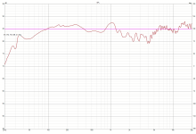
The farfield response shows a peak at 1khz which I assume is due to the port resonance (CMIIW), and a broad dip from 1.5khz - 6khz, which I think is due to the crossover not being acoustically aligned.
Following the guide to combine the three graphs, resulted in the following combined graph in VituixCAD:

Again the most noticable think is the 1khz peak and the broad dip in the XO region.
And I also don't know what causes the weird peak at 35hz.
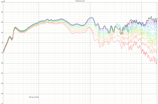
I think the horizontal dispersion was quite nice seeing the graph, showing no big dips/peaks as we move along the axis.


Overall, with this being my first build designed from scratch I'm not too disappointed with the result.
And I am planning to redo the crossover, this time with measurements capabilities.
I do hope to get some recommendations/insights though on what to do regarding the 1khz peak (if it is indeed caused by the port).
And also on the weird behavior in the LF (port output weird measurements)
Hope you enjoy reading this thread, and I'm looking forward forany input/recommendations/comments 🙂
JT
I just purchased a calibrated mic and has been measuring the finished speaker, following the step by step here: https://www.audiosciencereview.com/...ents-spinoramas-with-rew-and-vituixcad.21860/
Picture above shows the measurement of the port, woofer nearfield, and farfield at tweeter level (gated at 5ms)
A few things I noticed, on the woofer dip, usually on other measurements I've looked at, it usually is accompanied by a peak in the port output, but that doesn't seem to be happening here, and instead the peak is at ~35hz (which is lower than expected). I've measured again but this always shows up.
If someone knows why it is happening please let me know.
The farfield response shows a peak at 1khz which I assume is due to the port resonance (CMIIW), and a broad dip from 1.5khz - 6khz, which I think is due to the crossover not being acoustically aligned.
Following the guide to combine the three graphs, resulted in the following combined graph in VituixCAD:
Again the most noticable think is the 1khz peak and the broad dip in the XO region.
And I also don't know what causes the weird peak at 35hz.
I think the horizontal dispersion was quite nice seeing the graph, showing no big dips/peaks as we move along the axis.
Overall, with this being my first build designed from scratch I'm not too disappointed with the result.
And I am planning to redo the crossover, this time with measurements capabilities.
I do hope to get some recommendations/insights though on what to do regarding the 1khz peak (if it is indeed caused by the port).
And also on the weird behavior in the LF (port output weird measurements)
Hope you enjoy reading this thread, and I'm looking forward forany input/recommendations/comments 🙂
JT
Attachments
The spl level of the port peak at 35Hz seems too high: have you scaled the level of the port down (tipically 8-9dB) accordingly to the ratio of the area port/cone?
Below you can see a mini speaker that is very similar to yours (15x30cm) and you should have something like that in merger tool. The peak can be reduced by means of stuffing material.

Below you can see a mini speaker that is very similar to yours (15x30cm) and you should have something like that in merger tool. The peak can be reduced by means of stuffing material.
Last edited:
Well there is lots of information to sift through here.
You could try stuffing the port and seeing if you loose the bump,?
At the same time do impedance sweeps with the port open and then with with bung in place.
Even though you have modelled it and are using a calculate port length they can end up being shorter than calculated. I don't know how easy it would be for you to adjust the port lengths so maybe stick with the stuffed port idea for now.
I think the little wrinkle just past 1K is real and you can see that in the manufacturers data. Unrelated info the BBC LS3/5a had a bit of a hiccup at around 1Khz in the earliest incarnations but that was sealed Some people like it, lots don't.
I have heard the SB19 sounding sweet when close to a B3 alignment for 4Khz with a level resistor to taste then 4.7uF, 180mH and 8.2 uF with 3.3uF in parallel with the tweeter ( to bring the top end down). But that was on a slightly different baffle and the tweeter mounted off centre to reduce diffraction. I am sure you have looked at the SB crossover data where they have used the SB19 themselves.
As to the dip I think that is maybe a little more work on the slopes and how the woofer decays, if you tame the very top end of the tweeter the dip wouldn't be so bad and lots of people like the slight dished profile. trying to improve the power and directivity a little bit more maybe useful.
A question, if you hit the perfect curve shape, or as you more closely approach it what happens to the design if you do not personally like it. What I am saying here is if you can move it from the meh stage to being enjoyable for yourself then maybe enjoy them and listen to the music.
Nasib baik.
- Home
- Loudspeakers
- Multi-Way
- First Design - SB12PFCR25-4 + SB19ST-C000-4