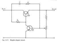
This circuit is from "Low Noise Electronic Design". It inverts the ripple on the input and modulates the drive of the pass transistor base. I suspect that it isn't too stable.
1) Motchenbacher, C.D. and Fitchen, F.C. "Low Noise Electronic Design", John Wiley & Sons, 1973
1) Motchenbacher, C.D. and Fitchen, F.C. "Low Noise Electronic Design", John Wiley & Sons, 1973
Attachments
The null will not be deep, but even a 10dB reduction for the price of a cap and an R may be worth it.
Jan
Jan
If RL is split, and a capacitor is added at the junction point, it will become a regular cap-mult, but helped by the open-loop reduction. R would then need to be made much larger.
The scheme might overcome the 60~70dB limit of a standard cap-mult, caused by the Early effect
The scheme might overcome the 60~70dB limit of a standard cap-mult, caused by the Early effect
That brings back memories.
I used this in regulated power supplies back in the seventies (and recently prepared it in my TO39 power supply as well (R15/C7)).
C was around 470 nf and R was around 1 Mohm. R initially was a trimmer.
Back then I helped myself in the following way: I connected the supply output to the microphone or phono input of an amplifier (+speakers/headphones) via a resistor and a small capacitor. When turning the volume control towards maximum, a slight hum could be heard, which could be minimized by trimming R.


Or simply accept a second Vbe of in-to-out voltage drop; merely connect two conventional (R-C-Q) filters in series. Instead of "N" dB's of PSRR you now get "2N" dB's. If one gives you 40dB (100x), two give you 80dB (10,000x).
You should stick to the original, with a NPN for Q2.Should I try different component values?
In addition, it would be preferable to adopt a more deterministic approach for the bias of Q2: a fixed base divider instead of the potentiometer + an emitter resistor.
If all this is combined with my previous suggestions, the circuit could become usable practically; R would need to be adjustable to suit the Vaf of the pass transistor
Below is my above mentioned regulator (simplified) from around 1972, with "ripple clipper".
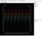
Output voltage 30V, simulated current 1A
I add the .asc file.
The graph shows V(out) with different values for R (R1/rr in asc-file).
light green 100k
yellow 150k
red 300k
dark green 1000k


seems to work best with R around 150k 🙂
Output voltage 30V, simulated current 1A
I add the .asc file.
The graph shows V(out) with different values for R (R1/rr in asc-file).
light green 100k
yellow 150k
red 300k
dark green 1000k
seems to work best with R around 150k 🙂
Attachments
Last edited:
You should stick to the original, with a NPN for Q2.
Oh, that was a mistake. Thanks! It was reversed. This one looks interesting. It's slow start, it takes it about 10s to get at max current. There's a 10000uf cap after rectification (before VCC).


Last edited:
I also made a simulation of the original circuit. Unfortunately nulling works only for a fixed load, which makes the circuit useless as a power supply.
The original circuit shown in the first post is certainly only intended as a basic circuit diagram and cannot be implemented directly as an independent circuit. But the principle works quite well, as my circuit simulation shows. The functionality varies somewhat depending on the output current, but in any case the ripple suppression is better than without the two components. Definitely useful for preamp power supplies where there aren't large current fluctuations. In a narrower output current range, attenuation of the ripple voltage by more than 20db is possible. (if I haven't miscalculated).
Drawing about 600ma. Looks interesting for a preamp... (This graph R5=30 for 600mA). Second graph has a 10.000uF cap with the load.


Last edited:
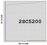
... the 60~70dB limit of a standard cap-mult, caused by the Early effect
So it's a pretty good idea to hunt for pass transistors with the least Early effect. Here's a potential candidate; good by itself, and wonderfully excellent in a cascode pair.
_
Attachments

That's a plain vanilla discrete regulator helped by a hum-bucking scheme, not a ripple clipper or eater.
A regular cap-mult adapts itself to the input voltage and provides 60~70dB ripple rejection using a single transistor (or integrated darlington for higher currents)
A regular cap-mult adapts itself to the input voltage and provides 60~70dB ripple rejection using a single transistor (or integrated darlington for higher currents)
If they are carefully (and individually) selected, no: they can improve the PSRR but opting for a suitable topology to begin with is the first priority. Such small embellishments can then be added to improve the performances further if needed
So it's a pretty good idea to hunt for pass transistors with the least Early effect. Here's a potential candidate; good by itself, and wonderfully excellent in a cascode pair.
SiGe transistors like BFP640 can have Early voltages in the KV range but are probably
dangerous in the hands of an average AudioHead. (Hint: 0603 50 Ohm bead close in the base)
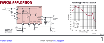
Also I cannot understand how 20 dB more suppression can provoke such a joy when
modern-day regulators provide > 110 dB at hum frequencies, along with metrology
grade voltage precision and 2 nV/rt Hz noise density. (LT3042, 45, LT3094 neg)
And at high frequencies you can help the regulator easily with cheap non-special parts.
I'd be ashamed if there was a spot on a board of mine where I needed 110 dB suppression.
Gerhard
Attachments
Last edited:
- Home
- Amplifiers
- Power Supplies
- Ripple Clipper or cap multiplier