Hello,
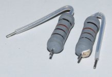
I desoldered 2 resistors from a bad switching supply.
With a multimeter and a LCR meter I found 660 ohms. But it's not what I read with color code.
There was a black Heat shrink tubing around. Pcb is burned below resistors.
What replacement parts do i order ?

I desoldered 2 resistors from a bad switching supply.
With a multimeter and a LCR meter I found 660 ohms. But it's not what I read with color code.
There was a black Heat shrink tubing around. Pcb is burned below resistors.
What replacement parts do i order ?
Attachments
Last edited:
Black - brown - orange: 1k
Black - orange - brown: 30 Ohm
Hard to tell but 1k is more common and the 4th band is a little more seperated.
A schematic would clear things up.
Hugo
Black - orange - brown: 30 Ohm
Hard to tell but 1k is more common and the 4th band is a little more seperated.
A schematic would clear things up.
Hugo
The paint's cooked so won't be the original colours. The resistance may have changed too. These look like metal oxide type, which ought to handle heat well (sintered RuO and glass), so perhaps they are 680 ohms? Best to be sure with a SMPS, and there may be other damage to track down too.

Not have schematic 🙁
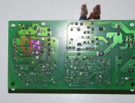
Placed at the secondary side followed by some capacitors. As Mark said surely not the original colours. Measures give the same value... 660 ohm. What are the probabilities for two resistances to be damaged the same way ?
If I can avoid more destructions 😉
Placed at the secondary side followed by some capacitors. As Mark said surely not the original colours. Measures give the same value... 660 ohm. What are the probabilities for two resistances to be damaged the same way ?
If I can avoid more destructions 😉
True, something else likely killed them if they have been overstressed. Time for the dim bulb limiter.
I would have said 1k looking at those. Fwiw I've come across metal oxide resistors pretty extensively in TV and VCR work where they were commonly used and yes, they can go low in value.

the only thing I'm pretty sure is the last ring that appears to be gold. I can't tell for others.
Color arrows figure resistances. Afters resistances there are 220uF 50V caps.

Color arrows figure resistances. Afters resistances there are 220uF 50V caps.
Well... No resistor value starts with black as black is zero.Black - brown - orange: 1k
Black - orange - brown: 30 Ohm
1 kΩ = brown, black, red (assuming ±5% or worse tolerance)
30 Ω = orange, black, black (assuming ±5% or worse tolerance)
The tolerance band is the band that's further away from the others. Black is not a valid colour for tolerance. I'm going to guess that was gold (±5 %) at one point. MOX resistors are generally not better than ±5 % anyway, and it looks like it was part of a snubber, so replacing it with a ±5 % type is probably fine.
It's pretty clear on my monitor that there are three different colours: Black, dark brown, and light brown. If we assume that the three rings were different colours to start with, 1 kΩ (brown, black, red) makes the most sense. 1 kΩ sounds high for a snubber, though.
I would scour the 'net for pictures of the supply and see if you can glean the colours on the resistor from those.
Tom
Last edited:
On second thought: Is the white 6-pin connector the output? If so, could they simply be bleeder resistors? If so, any value will do. Just observe the power dissipation so you don't cook the board any further.
They could also be there to ensure the supply sees a minimum load. In that case 1 kΩ or 12 kΩ (brown, red, orange) could be right.
Do you have an idea of the output voltage of this supply?
Tom
They could also be there to ensure the supply sees a minimum load. In that case 1 kΩ or 12 kΩ (brown, red, orange) could be right.
Do you have an idea of the output voltage of this supply?
Tom
I feel you may have guessed it... Following pcb, resistance is connected to a 220uF cap.
On the label v1 +24V/700mA and V2 24V/500mA
On the label v1 +24V/700mA and V2 24V/500mA
Were there three of them? It's clear that the board has room for three resistors.
12 kΩ across 24 V is only 48 mW, though. That's not enough to turn a resistor like that into char. Judging by the dimensions, it's probably a 1 W resistor. Maybe 2 W. 1 W @ 24 V -> R = 576 Ω. Only a fool would run the resistors right at their dissipation limit, so if we figure they were derated by a factor of 2x, we get 1152 Ω. Could they be 1200 Ω (brown, red, red)? Maybe the middle of the resistor was a bit cooler so that red stripe turned a lighter brown than the red stripe closer to the top...
There are some types of MOX resistors that can handle higher temperatures. I use some 3 W types that are barely larger than the old style 1 W ones. Just hop on Mouser/Digikey and search for metal oxide resistors (or power resistors more broadly). Use the selection filters to narrow your search and pick the highest power resistor that'll fit on the board.
Tom
Maybe see if you can find photos of that board online, and see if your can read the color coding from that ?
Of course. I wonder how I came up with that. 😱Well... No resistor value starts with black as black is zero.
- Home
- Design & Build
- Parts
- What should I trust ohm-meter or eyes?