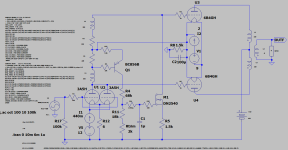
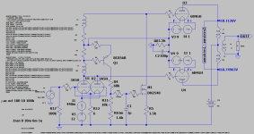
I have picked up an old idea that Slagle once came up with. If I remember it correctly, Rod kindly helped me with the servo. I have now "updated" it with DHT driver and "free lunch" anode voltage for the driver through a CT LL1667 anode choke.
Question is how to feed the PP heaters with Rod´s regulator?
For some reason it sims better with parallell heaters,
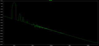
SE style FFT footprint. Below simmed at 5W giving ca 0,7% THD.


Question is how to feed the PP heaters with Rod´s regulator?
For some reason it sims better with parallell heaters,
SE style FFT footprint. Below simmed at 5W giving ca 0,7% THD.


Attachments
The idea of a single unit for PP heating was discussed a long time ago - but in practice it affects the sound too much.
The two PP valves have anode current flowing in the filament in antiphase (180° apart). The anode current produces a signal-voltage across the filament.... and connecting the two filaments in parallel creates a crosstalk between them.
PP filaments should be heated separately for good sound!
The two PP valves have anode current flowing in the filament in antiphase (180° apart). The anode current produces a signal-voltage across the filament.... and connecting the two filaments in parallel creates a crosstalk between them.
PP filaments should be heated separately for good sound!
Having being away from electronics 10 years I have lost a lot of knowledge. Thanks for explaining Rod, actually what I suspected after reading your precautions in the Bartola article, but hoped for a little more economic solution like in 4, 5 and 6 😉. Haven´t looked into it, I guess four regulators can not be fed from a single supply, so do I need two or four?
https://www.bartola.co.uk/valves/dht-push-pull/
“The important thing is that the currents flowing in opposition may well degrade the sound. Possibly, it will degrade it very badly! I would try it out, and listen – but a good outcome is not guaranteed!”
“The music signal current in each of the PP sides is in anti-phase, like the cathode current (in fact, it is the cathode current!). Since any improvement in filament supply quality can usually be heard, I would suspect the parallel connection sounds worse than individually regulated DHTs.
Series might be better, but I would check by listening for a long time.” (Rod Coleman)
https://www.bartola.co.uk/valves/dht-push-pull/
Last edited:
These put the Filaments in series.... Now the problem is that one « cathode » is biased below ground; the other is above ground. So the grid-cathode voltage is offset. The isolation is not so good, either.but hoped for a little more economic solution like in 4, 5 and 6
You can use the same DC feed for PP filaments, but only if the cathode voltage is the same point (eg ground - with grid bias).
You still need a L and R channel Raw DC though...
Just to settle the issue for yourself . . .
Build two mono-blocks, one with parallel heaters, one with separate heater power. Next . . .
Mount a DPDT switch in a metal box; an RCA input jack; two RCA output jacks; and 6 Banana jacks (3 red and 3 black).
Wire the switch wiper to connect the RCA input jack, so it connects to one, or the other, of the two RCA output jacks (depending on the switch position)
Connect all 3 black banana jacks together (ground, common).
Connect one red banana jack to the switch wiper, label that Output to Speaker.
Connect the other switch terminals, one to one Red banana jack (mono-block 1), and the other to one Red banana jack (mono-block 2).
Connect the left channel output of a CD player, Preamp, or other signal source to the RCA input jack.
Connect your left speaker to the speaker output banana, and one black banana jack.
Connect one mono-block output to one set of red and black banana inputs on the box.
Connect the other mono-block output to the remaining set of red and black banana inputs on the box.
Do not pay any attention to which switch position connects to which mono-block.
Invite your friends, audio fans, musicians, etc., including lots of women (good hearing), to come to your home.
Now, conduct a double blindfold listening test, play a variety of good recordings.
That is lots of trouble, but it will do something that no simulation software we have today can do . . .
Tell us what the listeners will hear, not hear, and the mix of opinions you get.
You do not need Stereo to perform this test.
One switch box, one mono-block circuit version 1, and another mono-block circuit version 2.
A stereo amplifier also works just as well, if you make the left channel with parallel filaments, and the right channel with 2 separate filament supplies.
Happy Proofs!
Caution about my proposal for a switch box to do double blindfold testing.
Some amplifiers can destroy themselves if they do not have a load, even though there is no input signal applied.
Please read my post here:
https://www.diyaudio.com/community/...hicon-fz-fz-kemet-peg124.406532/#post-7534725
Some amplifiers can destroy themselves if they do not have a load, even though there is no input signal applied.
Please read my post here:
https://www.diyaudio.com/community/...hicon-fz-fz-kemet-peg124.406532/#post-7534725
Thanks Daniel, its been 10 years since I visited diyAudio. Wonder how long ago it was, since I picked up the heavy 150Hz Tractrix from your place? Got a HiFi relapse after having spent to much time with hoktuna 😉 .
revintage,
No matter the circuit topology, using parallel filaments, or individually powered filaments . . .
The sonic differences are not proved by simulation programs.
And they are not proved without carefully designed and carefully conducted double blindfold listening tests.
Ask me how I know.
Just my opinions and my experiance.
Why did I post in this thread, because . . .
this thread had the following statements:
of a single unit for PP heating was discussed a long time ago - but in practice it affects the sound too much.
“The important thing is that the currents flowing in opposition may well degrade the sound. Possibly, it will degrade it very badly! I would try it out, and listen – but a good outcome is not guaranteed!”
That must have been almost twenty years ago now? Time to finish those horns now 😎Thanks Daniel, its been 10 years since I visited diyAudio. Wonder how long ago it was, since I picked up the heavy 150Hz Tractrix from your place? Got a HiFi relapse after having spent to much time with hoktuna 😉 .
Moving back to my roots in Varmland this spring. Actually thought about making something of them in the new listening room. Have cut the throats square and will use 414-8A(compression 1,8:1) with a 40l vented box behind. Have actually cut all the MDF pieces. Simmed them in Hornresp and they will go down to 60Hz. I am rusty with that program too, but want them to go somewhat lower without go big to the optimal 140l. Took me two late evenings to relearn LTSpice😱.
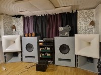
Sounds like a good plan! I went back to "hornflex" cabs a couple of years ago after getting tired of having half the floor space occupied by two 75Hz exponential midbass horns. Works fairly well with 18Sound 12" drivers (12MB600? Can't remember the exact model) and a bit of BSC-filtering to tame the overly enthustiastic midbass/ lower midrange.Actually thought about making something of them in the new listening room. Have cut the throats square and will use 414-8A(compression 1,8:1) with a 40l vented box behind. Have actually cut all the MDF pieces. Simmed them in Hornresp and they will go down to 60Hz.

Great looking setup! Hornflex seem to work fine, hoktuna uses 816 with 416. Will see what I can come up with. Might message you if I get stuck in Hornresp.I went back to "hornflex" cabs a couple of years ago after getting tired of having half the floor space occupied by two 75Hz exponential midbass horns.
I'd be glad to share my experiences after 3-4 built prototypes and numerous simulations. Though, perhaps a thread about hornflex designs would be even better as the discussion might be of interest for other forum members?Might message you if I get stuck in Hornresp.
Why not, it might be something when I have digged into it. Will be back......Though, perhaps a thread about hornflex designs would be even better as the discussion might be of interest for other forum members?
Hi 6A3sUMMER,
Note we are discussing an embryo of a novel amp circuit here.
novel?
What type of novel is?
Can you call it tube amplifier?
Only with simulation?
Built it, measure it then you can explain at the best if it will run properly
Walter
Not quite... you still need separate regulators, to prevent crosstalk between the antiphase PP halves.
But if the cathode resistor is shared (or zero) the Raw DC (rectifiers, caps, transformer) can be a single unit
- Home
- Amplifiers
- Tubes / Valves
- PP with Rod Coleman CCS heater regulators
