Hi!
I'm trying to get rid of oscillations in the MC part of the phono stage of the Cyrus Two Issue 07 amp, but to no avail. The amp belongs to a friend, he complained about no sound on left channel over phono (MM). It was "overhauled" years ago, but only C43/C44 were changed back then. I found almost all caps were dry and the RIAA opamp (A5) was oscillating.
I changed all electrolytic caps except main filter caps and renewed the regulators. After that, the amp seems to work fine, but now I have oscillations on both MC opamps. I added 100n to the C67/C68 and C72/C71, I tried even to add some capacitance directly to the opamp leads - no change. C3/C4 were not populated on the board, but they are not marked as "deleted" in the part list. Added them, but still no change. Any other steps I could do, before I disable MC section completely?
Thank you!
I'd check out the supply lines , lm317/337 and the lm394 integrity or hfe before the ne5534 compensation capacitor or a shorted styroflex.
https://www.vintage-radio.net/forum/showthread.php?t=131881
I wouldn't just fix this toy.I'd refurbish it completely.
https://www.vintage-radio.net/forum/showthread.php?t=131881
I wouldn't just fix this toy.I'd refurbish it completely.
Of course it will be refurbished to some extent, the switches will be dismantled and cleaned 🙂 The heater (LED supply🙂 needs attention, too.
It's just weird that before recapping and regulator change the MC section didn't oscillate.
Caps are all high quality Nichicon muse NP for bipolars and Nichicon/Panasonic FC for the rest.
It's just weird that before recapping and regulator change the MC section didn't oscillate.
Caps are all high quality Nichicon muse NP for bipolars and Nichicon/Panasonic FC for the rest.
I learned the hard way that some brands of LM317 require a run-of-the-mill electrolytic output capacitor for stability. Connect a capacitor with insufficient losses and the LM317 may oscillate - or sometimes oscillate and sometimes not. I had used ceramic X5R capacitors, which typically have a tan(delta) of the order of 0.02, about a decade lower than ordinary aluminium electrolytic capacitors. They sometimes produced an audible beep (X5R capacitors are piezoelectric and can act as loudspeakers), most of the time they did not.
A too large value for C3 will probably worsen stability. I would leave C3 not mounted, and try 100 pF for C7, unless the manufacturer recommends some other value. 100 pF should be a bit on the high side for C7, but that will only improve stability (at the expense of somewhat more distortion).
A too large value for C15 can also make the circuit instable, while it should be stable without it.

Who is Bruce Hofer?
The MC stage also has a lot of extra loop gain due to the extra input stage.
If the extra input stage had infinite bandwidth, C7 should be 22 pF times the gain of the extra input stage divided by the attenuation of the feedback network, which should boil down to about 33 pF. I think there is a good chance that the phase shift of the extra stage is small and 33 pF will work fine, but just to be sure, I would try a higher value first.

This compensation adds an additional pole to the open loop gain, i.e. gain rises with decreasing frequency at 12dB/octave rather than only 6dB/octave. It's conditionally stable, a great technique, but shouldn't be used without careful design and testing. See the following to see the technique on steroids: https://www.diyaudio.com/community/...ee-pole-compensated-class-b-retro-amp.385080/Not sure why Bruce Hofer went for the split series 47pf , but 22 pF always worked for me with ne5534 and the mc preamp has a lot of gain anyway.
BTW, in the C27 in post 3 is undesirable and should be deleted, IMHO. It does nothing useful and is only a liability.
C7 and C15 are not populated, no changes here.What are the values of C7 and C15 and did that change?
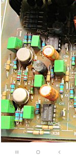
C7 appears to be deleted from the service manual and the philips caps c10, c11 are the real compensation caps for the ne5534 in the mc input stage.By their size I'd say they can't be bigger than 22pF...
C10 is a 6.8 nF supply decoupling capacitor in the schematic and a single-layer NP0 capacitor in reality. Apparently the schematic doesn't match what is on the board.
Hi, on this photo, there is another revision of the amp, probably issue 06. C11/C12 are 47 pf there.C7 appears to be deleted from the service manual and the philips caps c10, c11 are the real compensation caps for the ne5534 in the mc input stage.By their size I'd say they can't be bigger than 22pF...
Cautionary advice: make sure you're probing with a x10 probe; the load cap of a x1 probe can provoke oscillation in circuits that might otherwise be stable.
This MC design is a bit of a mess and I'm not surprised it oscillates, especially with C7=0. C7 would need to be 22pF for unity gain stability of the NE5534, but its designated gain is higher than 1 to begin with: Assuming for the moment that C3=0, the R9/R11 divider presents a gain of about 0.015, or about -36dB. The tail current into the discrete pair is about 10mA, so I estimate the discrete stage presents a gain of roughly 90 to the opamp's differential inputs, or about +39dB, for a gain of +3dB applied to the opamp. Oscillation isn't a surprise, I think. As a test, I suggest deleting C3 (as recommended by Marcel) and installing C7=470pF. This is not a remedy, only a diagnostic test to see if the circuit stabilizes. Adjusting C7 may be a fix, but 470pF is probably too much and needs study.
There are other issues that give me pause. The regulators and their output caps seem to be under suspicion; are they innocent, and only the MC stage(s) at fault? The supply bypass caps on the MC stage seem unusually small, and I don't see any bypass for the other opamps indicated on the schematic.
I'm not familiar with MC cartridges; the circuit loads the cartridge with 100 Ohms (R1). Is this standard practice?
Edit: external gain changed to net +3dB
Last edited:
Removed the C3 and added 33 pF C7. Seems perfectly stable now, thank you very much 🙂 I'm curious why the manufacturer deleted it and why/how/whether did it work before? 🤔Who is Bruce Hofer?
The MC stage also has a lot of extra loop gain due to the extra input stage.
If the extra input stage had infinite bandwidth, C7 should be 22 pF times the gain of the extra input stage divided by the attenuation of the feedback network, which should boil down to about 33 pF. I think there is a good chance that the phase shift of the extra stage is small and 33 pF will work fine, but just to be sure, I would try a higher value first.
Maybe c3 was higher value then maybe changed to smth else or just had lower losses 40 years ago...it also happens that old IC's behave differently when new than 40 years later and what constituted overcompensation is not enough today. I've seen it on a few ocasions and got no explanation why other than maybe inconsistent manufacturing process decades ago.Capacitor losses develloped over the years can be a factor . Ignoring manufacturing datasheet was the norm in the old days.Engineers used to calculate and measure everything. Today's engineers can't survive a week in open spaces without the manufacturer's app notes...I remember having a discussion on Jim Williams app notes based on Baxandall resonant inverters where he used the tank coil in a different place and the guy I was talking said that an entire industry who bought LT devices followed his footnotes, but Baxandall did it the right way and when I checked his assumption on the scope he and Baxandall was right and Jim Williams was wrong...So today's quote: Never doubt Baxandall and ne5534 datasheet 🙂 !Removed the C3 and added 33 pF C7. Seems perfectly stable now, thank you very much 🙂 I'm curious why the manufacturer deleted it and why/how/whether did it work before? 🤔
Last edited:
- Home
- Amplifiers
- Solid State
- Cyrus two phono stage oscillations