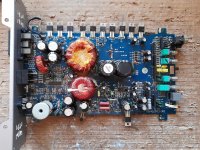
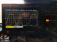
Amp clips unevenly with no load attached, with load it cannot drive it properly, sinewave gets distorted and the top half is being cut off.
Rail voltages are equal, aux voltages are fine. New driver IRS2011, new gate resistors, diodes, recapped and etc. Nothing is heating up, no abnormal current draw.
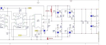
Schematic is attached, but it's a different revision than mine.
There are two resistors which are not present in the schematics but are in my board (check drawing). These have been changed in the past by someone else and i'm not sure the value of 100ohm is the correct one.
Amp uses fb31n20d but as these are obsolete i've tried so far with no avail with outputs as:
IRF1310N
IRF640N/IRF540N
IRFB4227
IRFB5615
SSP45N20A
I'm also using bipolar electrolytic capacitor instead of a film one for C83 as I don't have film one 10uf.
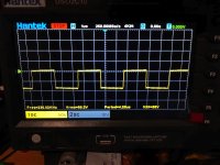
Logic input for low and high side gate driver outputs at the ir2011s are same regarding amplitude (HIN+LIN).
So is it something with the feedback circuit or these resistor should be 100Kohm instead of 100ohm ?
Rail voltages are equal, aux voltages are fine. New driver IRS2011, new gate resistors, diodes, recapped and etc. Nothing is heating up, no abnormal current draw.
Schematic is attached, but it's a different revision than mine.
There are two resistors which are not present in the schematics but are in my board (check drawing). These have been changed in the past by someone else and i'm not sure the value of 100ohm is the correct one.
Amp uses fb31n20d but as these are obsolete i've tried so far with no avail with outputs as:
IRF1310N
IRF640N/IRF540N
IRFB4227
IRFB5615
SSP45N20A
I'm also using bipolar electrolytic capacitor instead of a film one for C83 as I don't have film one 10uf.
Logic input for low and high side gate driver outputs at the ir2011s are same regarding amplitude (HIN+LIN).
So is it something with the feedback circuit or these resistor should be 100Kohm instead of 100ohm ?
Attachments
Last edited:

This is without the mosfets in.
What's the DCV across C85? = 0.33v
DC offset across speaker terminals? = no dc, but no output mosfets in
Audio clean coming into and out of U17 clean? = Yes, clean as it should be.
Should I put some mosfets in and measure once again, then with or without load ?
Should I use another value for C85?
What's the DCV across C85? = 0.33v
DC offset across speaker terminals? = no dc, but no output mosfets in
Audio clean coming into and out of U17 clean? = Yes, clean as it should be.
Should I put some mosfets in and measure once again, then with or without load ?
Should I use another value for C85?
Last edited:
If I fit some mosfets in.
What's the DCV across C85? = 9.7v
DC offset across speaker terminals? = less than 1 mv
Audio clean coming into and out of U17 clean? = still yes, clean as it should be.
What's the DCV across C85? = 9.7v
DC offset across speaker terminals? = less than 1 mv
Audio clean coming into and out of U17 clean? = still yes, clean as it should be.
Try C85 at a minimum as 10uF.
Unless you have a balanced differential voltage probe, you cannot check the bootstrap under operational conditions.
The C85 will always read the nominal DC voltage at idle, it's when the output is high that it must retain the voltage.
Unless you have a balanced differential voltage probe, you cannot check the bootstrap under operational conditions.
The C85 will always read the nominal DC voltage at idle, it's when the output is high that it must retain the voltage.
For this IC, I've never seen larger than a 1uF cap there. This amp, Infinity and the IR reference design all use 0.33uf. Page 50 of the following document.
https://www.infineon.com/dgdl/Infin...N.pdf?fileId=8ac78c8c85ecb34701866de8bb7b5297
Check the diode and resistor feeding that capacitor. As a side note, it was meant to be measured with the amp on with a multimeter.
https://www.infineon.com/dgdl/Infin...N.pdf?fileId=8ac78c8c85ecb34701866de8bb7b5297
Check the diode and resistor feeding that capacitor. As a side note, it was meant to be measured with the amp on with a multimeter.
As a side note, it was meant to be measured with the amp on with a multimeter. = this is what i've done.
Check the diode and resistor feeding that capacitor. = going to now. Resistor is exactly 4.7ohms, diode shows just fine.
What should be the supposed voltage across C85 ? 12v ? I do have only 9.7v.
Check the diode and resistor feeding that capacitor. = going to now. Resistor is exactly 4.7ohms, diode shows just fine.
What should be the supposed voltage across C85 ? 12v ? I do have only 9.7v.
Last edited:
I've never measure it on this IC but it's generally about 3/4v below the 12v regulator voltage for the IC. 9.7v should be enough but I'd expect it to be a bit higher.
What'e the voltage on the 12v regulator?
Can you measure the amplitude of the waveform on the high-side FETs (either a mains scope in differential mode or a handheld scope)?
What'e the voltage on the 12v regulator?
Can you measure the amplitude of the waveform on the high-side FETs (either a mains scope in differential mode or a handheld scope)?
What's the voltage on the 12v regulator? = 11v, no matter the b+ input
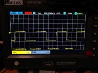
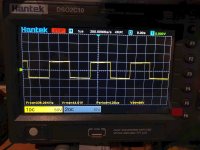
high side mosfet referenced to possitive rail.
gate
source
high side mosfet referenced to possitive rail.
gate
source
Attachments
Last edited:

Check all of the components in the 12v regulator. With a 15vZ, I'd expect more than 11v.
I don't know what to make of the waveforms. 8v of drive? I was expecting a waveform that was no more than 12vp-p. USe the scope in differential mode and measure source to gate (do not try this in normal mode).
I don't know what to make of the waveforms. 8v of drive? I was expecting a waveform that was no more than 12vp-p. USe the scope in differential mode and measure source to gate (do not try this in normal mode).
Changed the D27 zener, the Q1A tip41c, the D40 fr104 diode, R77A and R78...I do have voltage now between 11v and 13v depending on the B+.Check all of the components in the 12v regulator. With a 15vZ, I'd expect more than 11v.
I don't know what to make of the waveforms. 8v of drive? I was expecting a waveform that was no more than 12vp-p. USe the scope in differential mode and measure source to gate (do not try this in normal mode).
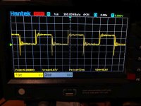
Same.... the top half sinewave gets clipped way to early. What've noticed is the point where it's starts to cutoff is rail voltage dependant . Increasing the b+, increases the rail, as my cut off point of the sinewave too. But even at 15v+ b+ it's still clipped.
Maybe this amp does not like any of these mosfets....i've have had in the past amps that won't work properly with anything except the fb31n20d or at least I could not make them.
Before it starts to clip, is the output from pin 1 of U13 relatively even then at the onset of clipping, it spikes on the top half?
To be clear, the rail is well over where it starts to clip, correct?
When you have 13 from the reg (I don't think it should be changing but I can't say for certain and the amp still clips at 13...), does the amp get any closer to the rail voltage?
In the previous rail-rail with the secondary ground, the amp was swinging ±50v. Is that what the rail voltage is in this amp?
Before it starts to clip, is the output from pin 1 of U13 relatively even then at the onset of clipping, it spikes on the top half? = Going to check now.
To be clear, the rail is well over where it starts to clip, correct? = Yes, correct. Both rails are stable and equal at +-52v.
When you have 13 from the reg (I don't think it should be changing but I can't say for certain and the amp still clips at 13...), does the amp get any closer to the r
ail voltage? = Yes it actually does ! The increase of the voltage from the regulator and respectively pin 1 at ir2011s, actually brings the clip point closer to the rail.
If B+ is 12v = Q1A emitter is 11.4v, pin 1 of the irs2011s is 10.7v
If B+ is 14.4v = Q1A emitter is 13.4v, pin 1 of the irs2011s is 12.7v
Rail voltages are +-52v at b+ 14.4v and +-43v at 12v b+.
Shouldn't the emitter of Q1A (Tip41C) keep the voltage constant ?!
The emitter follows the base. Is the voltage across the Zener changing in proportion to the emitter voltage (referenced to the negative rail)?
"The emitter follows the base. Is the voltage across the Zener changing in proportion to the emitter voltage (referenced to the negative rail)?" = yes it does.
Before it starts to clip, is the output from pin 1 of U13 relatively even then at the onset of clipping, it spikes on the top half?
- Home
- General Interest
- Car Audio
- Ground Zero class D issue (IR2011s)