I have built my first amp, a 5f1 from scratch about 2 years ago and it works perfect. I am following the original schematic, just removed the death cap and added a 3 prong cord.
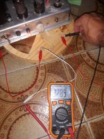
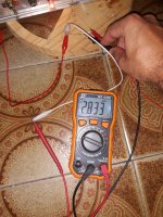
But I have made an experiment: plugged it into a non grounded outlet (only 2 pins) and if I measure with my simple multimeter (I have no LoZ) the AC voltage between the chassis and an earth ground I get about 328.9 vAC but if I put a 10k resistor in parallel with the multimeter probes I get only 2.8vAC.
Can I consider this normal (ghost voltage), may be due to some kind of capacitive coupling in the power transformer?
I checked all connections inside the amp and cannot find any short between high voltage windings and the chassis.
You can see photos of the measurements attached.
Anyway using the amp connected to a grounded outlet all works normally (no chassis voltages).
Thanks.
Attachments
It is normal to measure a high voltage between a floating chassis and earth, but I am surprised the number is higher than the wall voltage itself 🤔
Safety First!
Prevent: "The Surviving Spouse Syndrome".
A complete and accurate schematic is usually worth 1,000 words.
Sorry, I have no idea what a 5f1 amplifier is.
Prevent: "The Surviving Spouse Syndrome".
A complete and accurate schematic is usually worth 1,000 words.
Sorry, I have no idea what a 5f1 amplifier is.
I'm sorry, here is the schematic. Basically in the experiment I just put the multimeter in AC voltage measuring mode between the chassis and a earth ground, without having the 3rd pin of the power cord connected to earth ground.
 Relocated to the Instruments & Amps forum where the guitar amp expertise can be found.
Welcome to the forum! 😀
The leakage current is most likely the capacitance from the power transformer primary to the high voltage secondary (winding to winding; or winding to laminations to winding).
Now you know why so many different countries converted to a 3 wire power mains outlet standard.
Generally, there is more capacitive leakage current from a traditional power transformer than capacitive leakage current of a small dimension high frequency switching transformer.
I really like the 3 wire outlets in my house. My power amplifier designs all use the 3 wire IEC cords and sockets.
I am fortunate that my 2 wire tuners and CD players (all with switcher power supplies) do not cause interference in my various hi fi and stereo systems.
Unfortunately, my phono preamp uses an outboard switcher power supply, it does cause interference to every AM radio anywhere and everywhere in the house (including several battery powered radios that are not even plugged in).
It may not be very much leakage current. Even through only a few hundred pf at 60 Hz you’ll read full open circuit voltage. If the source impedance (all capacitive) is a few hundred k ohms and the load is the 10 meg impedance of the meter it will read just as if you connected it directly to the AC supply, transformer winding, or wherever it’s coming from. It normally wont be enough to bother you - if you touch it you end up loading it down, usually below a few volts. If leakage gets too high you’ll feel it and it becomes dangerous. If the voltage you measure across yourself gets above about 30 you at least start to get a tingle. The 3rd wire ground provides very low Z and prevents this buildup. Prevents similar buildup of static charge, too.

- Home
- Live Sound
- Instruments and Amps
- 5F1 chassis to ground voltage