Hi Guys.
I was planning a speaker project and wondered if anyone could help me with the calculation for a dual-woofer transmission line design.
I can find online calculators for single woofers but not dual, so I'm thinking I need some advice from your expertise 🙂
Many thanks for considering my request.
I was planning a speaker project and wondered if anyone could help me with the calculation for a dual-woofer transmission line design.
I can find online calculators for single woofers but not dual, so I'm thinking I need some advice from your expertise 🙂
Many thanks for considering my request.
On-line TL calculators should be considered a joke. Like any other box, it should be modeled, TL modelers thou are scarce on the ground. There is much more design space than for typical modelers.
For a dual driver TL, double the Vas. Fs, Qt remain the same. Zd should be set the average position of the drivers.
Do you have drivers in mind? What are your goals?
One of ours:
dave
For a dual driver TL, double the Vas. Fs, Qt remain the same. Zd should be set the average position of the drivers.
Do you have drivers in mind? What are your goals?
One of ours:
dave

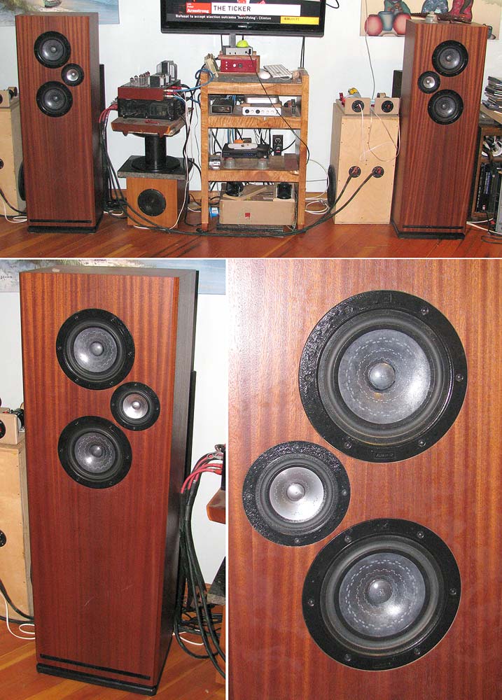
Looking at something with a big, clear, classic speaker sound but compact enough to keep my wife happy. That's why I thought of the *2 TL design
Nice looking driver. Hornresp can model 2 drivers if you go that way. And spicytl too I believe.
Last edited:
Seems tiny to me 😉, especially once stretched into a MLTL if no significant series R and/or use the late Professor Leach's preferred Qes and even then only pumps it up to 112.64 L/3.98 ft^3/38 Hz Fb:
T/S max flat alignment:
Vented net volume (Vb) (L) = 20*Vas*Qts'^3.3 = 30.86 L*2 = 61.71 L/2.18 Ft^3
Vented box tuning (Fb) (Hz) = 0.42*Fs*Qts'^-0.96 = 45.4 Hz
F3 (Hz) = Fs*0.28*Qts'^-1.4 = 51.4 Hz
(Qts'): (Qts) + any added series resistance (Rs): http://www.mh-audio.nl/Calculators/newqts.html
T/S max flat alignment:
Vented net volume (Vb) (L) = 20*Vas*Qts'^3.3 = 30.86 L*2 = 61.71 L/2.18 Ft^3
Vented box tuning (Fb) (Hz) = 0.42*Fs*Qts'^-0.96 = 45.4 Hz
F3 (Hz) = Fs*0.28*Qts'^-1.4 = 51.4 Hz
(Qts'): (Qts) + any added series resistance (Rs): http://www.mh-audio.nl/Calculators/newqts.html
The Seas unit does a pretty good job. The TLDesign tool gives convenient starting options for the sizing of the enclosure if you don't already have something in mind. Longish line length can be reduced by a reasonable taper. The ripple can be modelled and smoothed to taste.


Models nearly everything without hurting the brain :
https://www.aj-systems.de/indexe.htm
https://www.aj-systems.de/Pictures/Frontloaded2.png
https://www.aj-systems.de/indexe.htm
https://www.aj-systems.de/Pictures/Frontloaded2.png
Like @planet10 said "Zd should be set the average position of the drivers.". This covers both wiring options:

Thanks, Guys, much appreciated. Being a newbie this will give me plenty to add to my design and much to think about 🙂
Would two "woofers" design make sense with dual Alpairs 10.3... ?
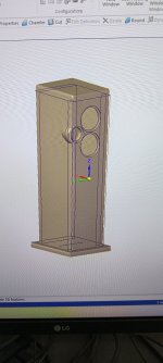
Im thinking something like this:
crossover at approx 2k
Jim's MLTL design but double volume to account for second driver, all centered like normal and as close together as possible, tweeter on side same as close as possible.
all drivers connected in parallel.
Measurments are in metric mm, used MDF 38mm to add weight and it should be easier to build / paint (+cheaper in CRO then 18mm ply...)
Thoughts ?
Attachments
Last edited:
Much like our big MTM, but adding tweeter to A10.3 makes little sense to me. Using them as woofers is also strange.
I’d think a WAW with woofers that go lower makes sense.
When i hear 2 x A10.3 i think Twin FHXL.
dave
I’d think a WAW with woofers that go lower makes sense.
When i hear 2 x A10.3 i think Twin FHXL.
dave
yes.. i realize it makes little sense since they are true fullrange (in proper box ofcourse)..
But i already have them (4pcs) and i want to use them all together and jims design and measurments are very impressive to me in the low range, if paired with good tweeter it could be very nice, not ideal but still.
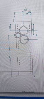
Does this arrangement work as per photos?
But i already have them (4pcs) and i want to use them all together and jims design and measurments are very impressive to me in the low range, if paired with good tweeter it could be very nice, not ideal but still.
Does this arrangement work as per photos?
Double the cross-section, get the drivers as close as possible, with their midPoint at Zd and add afilter to the bottom one — i’d connect in series
https://www.planet10-hifi.com/downloads/Dual-Driver-Wiring.pdf
dave
https://www.planet10-hifi.com/downloads/Dual-Driver-Wiring.pdf
dave
- Home
- Loudspeakers
- Multi-Way
- dual woofer transmission line