Something that always bothered me about the Keele CBT arrays, is that the loudest drivers in the array sit on the floor, and the quietest drivers in the array are at ear level!
This always seemed to make no sense to me, and in all of the CBT experiments I've done, I've shaded them so that the loudest drivers are in the center of the array, like every other array type does.
This afternoon I was running some sims in Vituixcad. When using the array generator in VituixCad, it puts the mic at the center of the array, by default.

But note that the HOTTEST driver in the array sits there on the floor.

Here's how things look with the CBT array, with the mic sitting on the floor.
These results made no sense to me; why is it louder OFF axis than ON axis?
I went digging through the help manual, looking for some type of solution, with no luck.

Here's how the array performs if you move the mic to ear level, or 36" / 914mm off the floor. Directivity control doesn't go as low, but now the polars look correct. In particular, it's louder on axis than off. (Note that we've changed the "on axis" point of reference to be 914mm higher than it was before. IE, we moved the mic to ear level.)
After pondering this for a little while, I think I figured it out:
Keele describes "halving" the array as a situation where the floor reflects the array like a perfect mirror. I'm not convinced this is the case; I haven't seen any data to support the idea that the floor can perfectly mirror what's above it.
But I do think that the backwards tilt, caused by the curvature of the CBT array, is moving the listening axis UP.
I've posted the data; this next part is a bit of speculation:
If you look at the profile of a CBT array, it points UP about twenty degrees. If you listen at a distance of three meters (fairly typical), that means that the focal point of the listening axis is 1.85 meters above the floor if there is no shading. IE, if the CBT was just a curved array with no attention whatsoever to the shading, you'd need to be standing to hear the maximum SPL and smoothest possible response from a CBT the size of a CBT24 (five feet tall.)
https://www.parts-express.com/Epique-CBT24-Line-Array-Speaker-System-Pair-301-982
All of us have messed around with the balance control on a set of stereo speakers. Turn the knob to the right, and it tends to 'shift' the soundstage to the right.
To an extent, I think the shading on the CBT is doing something similar:
1) The curvature of the CBT is aiming the listening axis up in the air. For a CBT24, if it wasn't shaded, the listening axis would be 1.85M off the floor, or about six feet tall. If you were seated, you would be outside of the optimal listening window
2) But by shading it, it has the effect of virtually moving the listening axis DOWN.
I never understood the scheme until today, but it's pretty clever if you think about it in layman's terms:
1) If you are listening to a CBT that's two meters tall, and you're seated and your ears are one meter off the floor, you have two things canceling each other out: The tilt-back of the array is pointing the listening axis about a meter above your head, but the shading on the array is dragging the listening axis back down
2) If you are listening to a CBT that's two meters tall, and you're standing and your ears are two meters off the floor, you have two things canceling each other out: The tilt-back of the array is pointing the listening axis right at your head, but the shading on the array is dragging the listening axis back down. If the array wasn't shaded, this height would be louder than any other height, because the array is physically pointed at this height. But the shading is 'pulling' the axis back down towards the floor.
3) If you are listening to a CBT that's two meters tall, and you're laying on the floor and your ears are just above the floor, you have two things canceling each other out: The tilt-back of the array is pointing the listening axis at a point two meters above you, but the shading on the array is dragging the listening axis back down to where you're ears are at (the floor.) If the array wasn't shaded, this height would be quieter than other heights, because the array is physically pointed at a spot two meters above you. But the shading is 'pulling' the axis back down towards the floor.
With all of that in mind, it seems like one might be able to simplify a CBT array by using a plain ol' flat baffle, but tilting it backwards and shading it. This should improve the WAF of the speaker, while also making it simpler to construct.
Some additional notes:
This always seemed to make no sense to me, and in all of the CBT experiments I've done, I've shaded them so that the loudest drivers are in the center of the array, like every other array type does.
This afternoon I was running some sims in Vituixcad. When using the array generator in VituixCad, it puts the mic at the center of the array, by default.
But note that the HOTTEST driver in the array sits there on the floor.
Here's how things look with the CBT array, with the mic sitting on the floor.
These results made no sense to me; why is it louder OFF axis than ON axis?
I went digging through the help manual, looking for some type of solution, with no luck.
Here's how the array performs if you move the mic to ear level, or 36" / 914mm off the floor. Directivity control doesn't go as low, but now the polars look correct. In particular, it's louder on axis than off. (Note that we've changed the "on axis" point of reference to be 914mm higher than it was before. IE, we moved the mic to ear level.)
After pondering this for a little while, I think I figured it out:
Keele describes "halving" the array as a situation where the floor reflects the array like a perfect mirror. I'm not convinced this is the case; I haven't seen any data to support the idea that the floor can perfectly mirror what's above it.
But I do think that the backwards tilt, caused by the curvature of the CBT array, is moving the listening axis UP.
I've posted the data; this next part is a bit of speculation:
If you look at the profile of a CBT array, it points UP about twenty degrees. If you listen at a distance of three meters (fairly typical), that means that the focal point of the listening axis is 1.85 meters above the floor if there is no shading. IE, if the CBT was just a curved array with no attention whatsoever to the shading, you'd need to be standing to hear the maximum SPL and smoothest possible response from a CBT the size of a CBT24 (five feet tall.)
https://www.parts-express.com/Epique-CBT24-Line-Array-Speaker-System-Pair-301-982
All of us have messed around with the balance control on a set of stereo speakers. Turn the knob to the right, and it tends to 'shift' the soundstage to the right.
To an extent, I think the shading on the CBT is doing something similar:
1) The curvature of the CBT is aiming the listening axis up in the air. For a CBT24, if it wasn't shaded, the listening axis would be 1.85M off the floor, or about six feet tall. If you were seated, you would be outside of the optimal listening window
2) But by shading it, it has the effect of virtually moving the listening axis DOWN.
I never understood the scheme until today, but it's pretty clever if you think about it in layman's terms:
1) If you are listening to a CBT that's two meters tall, and you're seated and your ears are one meter off the floor, you have two things canceling each other out: The tilt-back of the array is pointing the listening axis about a meter above your head, but the shading on the array is dragging the listening axis back down
2) If you are listening to a CBT that's two meters tall, and you're standing and your ears are two meters off the floor, you have two things canceling each other out: The tilt-back of the array is pointing the listening axis right at your head, but the shading on the array is dragging the listening axis back down. If the array wasn't shaded, this height would be louder than any other height, because the array is physically pointed at this height. But the shading is 'pulling' the axis back down towards the floor.
3) If you are listening to a CBT that's two meters tall, and you're laying on the floor and your ears are just above the floor, you have two things canceling each other out: The tilt-back of the array is pointing the listening axis at a point two meters above you, but the shading on the array is dragging the listening axis back down to where you're ears are at (the floor.) If the array wasn't shaded, this height would be quieter than other heights, because the array is physically pointed at a spot two meters above you. But the shading is 'pulling' the axis back down towards the floor.
With all of that in mind, it seems like one might be able to simplify a CBT array by using a plain ol' flat baffle, but tilting it backwards and shading it. This should improve the WAF of the speaker, while also making it simpler to construct.
Some additional notes:
- In the real world, if one is 'tweaking' a CBT, it may be useful to tweak the resistor values for the shading so that the curves are largely equal at various heights. IE, if you look at my shading, I chose the values using "optimum" values for the sim. The sim doesn't factor in the impact of floor reflectivity and the furniture in the room. In the real world, one could probably improve things quite a bit by tweaking those resistor values so that the measured output is consistent at different heights. By doing it in your room, you're compensating for what's in the room. This isn't like a typical crossover with inductors and caps, where modifying values has a cascading effect on all the crossover points. Because these are just resistors and for the most part all they're doing is manipulating the amplitude of the various elements. Easier to do this with DSP of course, but that would require a lot of channels of amplification.
- In the sims above, I'm using eight MCM 55-1870 midbasses. That's why the response above 3khz is all over the map; I'm not using the ultra wide bandwidth and small diameters drivers from a 'real' CBT. (My plan is to add a tweeter here, BTW)
Last edited:

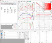
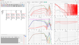
Here are sims of the vertical and horizontal response, and includes the layout of the midbasses in the array.
This is simmed with the microphone three feet off of the floor, or about where our ears are.
This sim includes directivity and baffle step, as generated using the VituixCad diffraction calculator.
It's interesting to note how low the efficiency is below 300Hz. Something I don't like about the arrays I've heard at places like Guitar Center is that they sound very 'thin.' I'd long assumed this had something to do with the tall/skinny shape of the cabinet. While that IS true, it looks like what these long skinny arrays need is a bunch of EQ to bring up the low end to match the lower midbass and midrange. Basically, those Guitar Center arrays would probably sound better with some EQ.
When I say "Guitar Center Array", I'm talking about all the prosumer line array stuff you see for sale in their pro audio departments, which are largely very tall/narrow arrays such as the ones from JBL and Bose.
Also note that the entire passive network consists of just two resistors. (For now. I intend to add a tweeter.)
Attachments
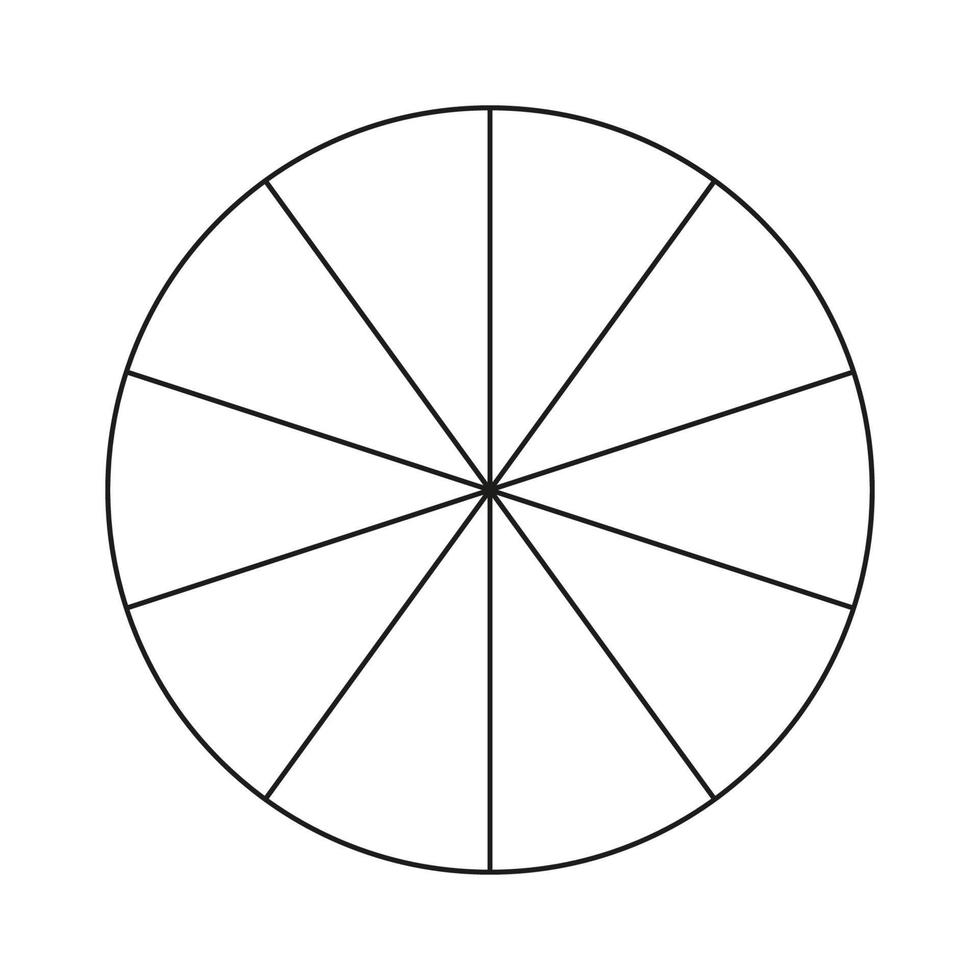
Closer to ideal could be a quarter hemisphere array wedged into the corners. You'd use no shading because there is no termination.
All models of JBL CBT loudspeakers seem to have straight enclosures with passive time delay circuitry to enable the time delay of curved cabinets. Looking at the circuitry within these speakers radiate with maximum sound output at midpoint of the cabinet and are shaded toward each end. These units are intended to be wall mounted for various pro sound applications. JBL claims (as does Don Keele in his papers) that CBTs create better sound energy coverage throughout the listening space vs. conventional PA speakers which cluster the sound energy near the front of the room.
Keele has compared free standing CBT arrays versus ground plane versions which stand on the floor. Keele’s “Brief Overview of CBT Theory” poster chart has a diagram entitled “Working Off the Side of the Pattern” which shows how the typical listening axis for a ground plane array is offset from the main axis of the array.
Keele states (on the Conclusions chart at the lower right) that CBT ground plane arrays have beneficial effects as the effective size of the array is increased while decreasing the physical size of the array. I suspect that Keele favors ground plane CBTs for home applications as they are more adapted to the space. Ground plane arrays do feature better bass coupling to the floor and minimizes reflections from the ceiling as well.
https://www.keele-omholt-technologies.com/papers/Keele Poster 1 (Brief Overview of CBT Theory).pdf
Jim
Last edited:
Another interesting set of plots from Don Keele's simulations vault compares a point source in free space and on a ground plane (top two plot groups). The two center plot groups compares a two way point source system in free space and on a ground plane. The bottom plot groups compare a straight line array and a CBT array both on a ground plane. He notes the near field effects and interferences for the straight array vs. the superior performance of the CBT when mounted on a ground plane.
https://www.keele-omholt-technologies.com/papers/Vertical Sound Field Simulations v10.pdf
https://www.keele-omholt-technologies.com/papers/Vertical Sound Field Simulations v10.pdf
I think you need to decide how much floor bounce bothers you. Don assumes 100% floor reflection and creates an array that has its radiation axis at 0 degrees and 0 height (it skims along the floor). Since the polar performance is really uniform then Don doesn't care if he is off the hottest axis (as his curves show) and response at a typical listener height will still be good.
As soon as you play with the shading to get the radiation axis and height at a sensible listening height then there will be some energy bouncing off the floor. This puts you in the same camp as any other conventional line array, where we are happy that the array directivity reduces floor bounce to some degree, certainly making you better off than a bookshelf speaker on a stand.
It wouldn't be hard to simulate an array plus its reflection (a second, attenuated, lower array) to see what amount of absorption gets "floor bounce" ripple down to an acceptable amount. A straight line array with alternative shading may get you to a happy result. It just won't be a CBT array.
The comparison between a straight line CBT (with electrical delay of the ends) and a curved array is interesting if you think about it. At small angles off of the primary axis there is no difference between electrical delay and physical delay. At greater angles it breaks down. Physical delay is always delay in the direction backwards of the forwards physical axis. Electrical delay is the same as always pushing units back away from the observer, no matter where you observe from. Works for small angles but not for large.
https://www.keele-omholt-technologies.com/papers/BW-801-Matrix-vs.-CBT36-v8.1.pdf
Not exactly a comparison to a bookshelf speaker on a stand but Don does compare a CBT to a B&W 801.
Not exactly a comparison to a bookshelf speaker on a stand but Don does compare a CBT to a B&W 801.
update -
I did a bunch of sims, intended to see if one could simplify the CBT by:
1) take a straight array
2) angle it backwards
3) then shade it
My thought was that it should be possible to simplify the construction and possibly improve WAF by using a straight line instead of an arc. Similar to how 60 degrees of a hexagon approximated a sixty degree slice of a circle.
Didn't work. The results weren't awful but they were noticeably poorer than an arc. Worst of all, it reduced how high the array could play, by quite a bit. I think this is because angling each driver by even five degrees creates a situation where it's high frequencies are 'aimed' as much as 30 degrees off axis from identical drivers located about 1-2 feet away. So the two drivers interfere with each other less, and this extends the highs. If our drivers were just one centimeter in diameter, it would be much easier to get the straight arrays and the unshaded arrays to perform better.
Did you apply the delays needed to simulate the units on an arc? I'm wondering if that is the secret sauce for CBT performance.
I've done that with a straight-line and CBT both built with the same set of 24 3" drivers. The drivers were mounted on a removable baffle, that fit into either the straight box or the CBT box.Did you apply the delays needed to simulate the units on an arc? I'm wondering if that is the secret sauce for CBT performance.
Drivers were wired in 6 groups of 4 drivers. With 6 amp channels. Both magnitude and delays could be set very finely.
But that limited the ability to do magnitude shading for the CBT, to 4 drivers per group, rather than 24 discrete channels as would be ideal.
By the same token, when trying to mimic the CBT with the straight-line, both magnitude shading and delays had to be set 4 drivers to a setting.
The straight-line did a pretty good job replicating the CBT, but not quite.
First thing I noticed listening to just one of each, was the CBT's apparent acoustic center (using ears) stayed at a pretty constant height on the speaker with varying listening distance. The straight-line CBT mimic center moved up and down the line more with listening distance.
In stereo, the CBTs held better imaging with different room placements. Maybe better tonal consistency too....but i would need to go back and check notes on that one.
I guess for a really valid test, 24 discrete channels would be needed. But i felt i learned enough from just 6 to skip that complexity....
- Home
- Loudspeakers
- Multi-Way
- Simplified CBT?