Hey,
Im having trouble finding why the output stage rails are 0V.
Friend brought the receiver to me. Told me that out of the blue there were sparks flying inside the case while he was casually listening to music while doing house repairs.
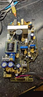
Took it apart, on the primary side the main mosfet had gone kaboom and took some diodes/pwm controller with it.
Swapped everything out and now receiver powers up fine but output stage is silent. EVERY other accessory voltage is present and at correct voltage but +/- rails for the output is at 0V. I have checked all the semiconductors and even took the transformer off to get to the optocouplers that are underneath it and everything seems to be okay.
Output stage itself seems to be okay and rail caps start charging when checking in continuity mode.
Maybe someone has come across similar problem?
Attached a pic of the psu unit.
Im having trouble finding why the output stage rails are 0V.
Friend brought the receiver to me. Told me that out of the blue there were sparks flying inside the case while he was casually listening to music while doing house repairs.
Took it apart, on the primary side the main mosfet had gone kaboom and took some diodes/pwm controller with it.
Swapped everything out and now receiver powers up fine but output stage is silent. EVERY other accessory voltage is present and at correct voltage but +/- rails for the output is at 0V. I have checked all the semiconductors and even took the transformer off to get to the optocouplers that are underneath it and everything seems to be okay.
Output stage itself seems to be okay and rail caps start charging when checking in continuity mode.
Maybe someone has come across similar problem?
Attached a pic of the psu unit.
Attachments
Last edited:
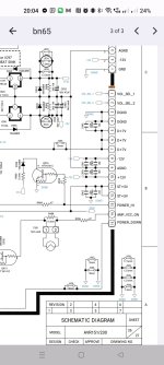
Still trying to figure out whats the problem. Could it be that the main mcu is shutting it down / not turning it on? On connector BN65 i have pins 13,14,15 which are POWER_HI, AMP_VCC_ON and POWER_DOWN. I have 4.8V on pins 13/14 and i have a 50hz square wave on pin 15 with ~3.6V rms. But i cant find what are the correct values for those pins or are they inputs or outputs.
Attachments
Hi there Jartzz!
I'm having the same issue. However, I'm currently stuck at the part with replacing components of the power supply. The 1.5R resistor R765 blew up as the n channel mosfet Q904 made a short between +vbat (the rectified input voltage) and GND. The problem is, that my power supply is different to the one from the service manual. In the service manual IC92 is an 8pin THT PWM controller, my board has a 6pin SMD controller. As it's impossible to find out from the IC marking, whats the manufacturer part number, maybe you could check/share if IC92 was broken in your case and with which part did you replace it?
To give an idea of your original question:
The 50Hz square wave looks okay for me. It's generated by an optocoupler from the mains voltage. I don't see the issue here.
Did you check the rest of the power rails, especially +-40V of the CN20 that supplies the amplifier stage?
I would be very thankful for any ideas!