After many years I think I have re-learned how to draw a load line. So see if this is OK. This is for a 6SF5 driving a 6V6 SE amp.
Ebb 265 V.
Rp - 250k.
Cathode resistor - 3.75k for 1.5 volts.
or
6.6k for 2 volts.
2 volts looks like it would have the best output voltage swing.
Sound right or am a missing something?
Ebb 265 V.
Rp - 250k.
Cathode resistor - 3.75k for 1.5 volts.
or
6.6k for 2 volts.
2 volts looks like it would have the best output voltage swing.
Sound right or am a missing something?
Attachments
markw51,
Too much bias voltage with a high resistance plate load, can cause the tube to operate too near to the cut-off region.
That causes the plate resistance to increase, and causes eccessive 2nd harmonic distortion.
The 6SF5 is very much like one triode of a 12AX7, except the 6SF5 filament draws 0.3A, and the 1/2 filament of a 12AX7 draws 0.15A.
A 6SF5 should be able to easily drive any 6V6 you can find (except worn out ones and dead ones).
The very succesful commercial Fi X 2A3 amplifier used a 6SF5 to drive the 2A3 (2 6SF5 for 2 2A3 stereo).
It seems that you may be starving the 6SF5 for current.
You are using 250k plate load in order to get lots of gain; but how much gain do you need to drive a 6V6 into positive and negative clipping?
I think I would consider using the top of the chart, and with EBB = 300V. You can use 100k for rp, and 240k for the 6V6 grid resistor.
Just my opinion of a place to start.
What do you think about that?
How are you using the 6V6?
Beam Power mode
Ultra Linear mode
Triode Wired mode
What is the output transformer's primary impedance?
Let us know how your amplifier comes out.
Have fun! Enjoy building, enjoy listening!
Last edited:

If I were building this I would do what I always do when venturing into the unknown. Build one channel as you describe, but in a manner where you can experiment. Here you only have two variables the plate load resistor and the cathode resistor. I simply put a pot in place of each resistor. Start with the values you have, 250K and somewhere around 4.5K. Leave the plate pot at 250K and play with the cathode pot. Record your observations on paper. Put the cathode pot back where you started (about 4.5K) and move the plate pot to maybe 200K and repeat the process with the cathode pot, recording your observations. Use the same source material for all testing. Make note of your "best choice."
Leave the amp alone for a day or two then repeat the process with different sources.
Yes, this takes some time and patience. Walk away when and if you get frustrated or feel that you can't make any progress or draw a conclusion. You may be listening to this amp for a long time. Work done up front is worth it.
Note that some of the old metal tubes can be quite microphonic while others are quiet even when whacked with a pencil. Some of these tubes are 70+ years old, there will be quite a bit of tube to tube variation and some will be outliers. Some just sound "off." Note that most of my experiments have been with old metal pentodes line the 6SJ7, 6AC7 and 6AG7. I have a few 6SF5's but haven't got to them yet. I have been collecting metal tubes for a guitar amp that I will call "MetallicAmp all tube, no glass." There will be no semiconductors or other parts that didn't exist before I was born (1952) in the amp.
Some of the circuits were developed with the techniques outlined above. I was experimenting with a pentode input stage that was loaded with a second pentode wired as a CCS for extremely high gains (up to 1000). There were three variables, the cathode, screen, and plate resistors. It took me over a month of tinkering to arrive at a combination of parts that I liked for the input stage. There were days that I never touched it, and days that I tinkered for hours. Seven different guitars were used.
The 6SF5 is a low Gm tube. You can get away with clip lead connections for the pots. The cathode resistor is usually bypassed so clip leads will work there on most any tube. This is not the case with the 6AC7 and 6AG7 as they will turn into RF oscillators with sloppy wiring. The 6SJ7 can be used with clip leads in some cases as can their 7 pin cousins like the 6AU6. You must keep the grid and plate wiring separated though.
The original Fender Champ used a 6SJ7 driving a 6V6. That's where I started out as a kid with a guitar and no amp in the 1960's. Dead TVs from the trash dump had plenty of sweep tubes, and Champ clones can be built on a pine board with tube sockets screwed to it using a 6SJ7 driving a 6BQ6GT. A 6V6GT did drop right into the same socket once I finally found one in the trash somewhere. I never saw a 6SF5 until I got to high school.
Thanks gents for the replies.
Tubelab: I am not building this as a guitar amp but as a hifi stereo amp. So fidelity is my main goal here. I am also a guitar player so am familiar with guitar amps but I no longer play electric. I got into classical and flamenco but that's another story.
6a3: The 6V6 will be in UL mode, although there is a switch for either UL or triode. This amp is really already built but using 6AK5's in the preamp stage. There is one of those tubes for each channel so I wanted to try an octal type that is more of an audio tube. The output transformers are Edcor 10 watt 5K. As for the supply voltage the power transformer is 250 - 250 with a 5U4g rectifier so getting 300 volts out would be difficult I think but I can squeeze more out of it than what I'm getting now.
If the 250V supply should not be enough, you can get more for the 6SF5 if you use the 5U4G only to supply the power tubes and make another supply for it. From the same secondary you can do another one in parallel. You can either do it as double-wave rectifier with solid state rectifiers and gain about the 5U4G voltage drop or configure it as voltage doubler and have very high supply. Given the low current draw of the 6SF5 it should not be a problem and can be effectively filtered with multiple RC cells.
markw51,
A 250-0-250 secondary has 350V peak at each lead. The voltage drop of a 5U4-G / 5U4GA is only 44Volts at 225mA load, and a 5U4-GB only drops 50V at 275mA. (your load is far less current, so less than 44V drop).
350V -44V, if you use a capacitor input filter, you should be able to easily get 300V at the first filter cap.
From there, a choke and second capacitor is plenty good for a 6V6 (a choke and its DCR after a cap input filter has more filtering and less voltage drop than using a resistor between the first and second filter caps.
And, I believe a 6V6 will like 300V B+, especially with a 5k output transformer primary.
Are you using a self bias resistor and bypass cap at the cathode?
I hope you are not trying to use a Choke input filter with 250-0-250V secondary to run the 6V6 and input tubes. (I Love choke input filters, but not with such low power transformer secondary voltages).
If you are not using negative feedback (other than local feedback of either UL mode, or Triode wired modes) comparison:
6V6 in Ultra Linear gives more gain and more output power.
6V6 in Triode wired mode gives less gain, less output power, less distortion, but does give a better damping factor that some loudspeakers need.
A 6SL7 dual triode octal audio tube (u = 70), can give enough gain for a pair of 6V6 tubes.
There always way too many things to try.
Have fun!
As always, Tubelab_com adds a lot to any thread. Lots of good advice and ideas.
He mentions the 6SJ7 sharp cutoff pentode. I always wanted to try one, and to try a 6SK7 remote cutoff pentode too; perhaps I will in the future (in pentode mode).
Note: If a 6SJ7 is connected in Triode mode, it is essentially a metal version of 1/2 of an octal dual triode 6SN7 audio tube (really close specifications).
Have fun experimenting.
Last edited:
Thanks again 6a3 for all the good advice. When I get it together I'll see what voltages I can get. The 6v6 tubes are cathode biased right now with a 300 ohm resistor for each tube and a bypass cap.
Here is an example of a 6SJ7 / 6V6 amp that was actually built just after the Earth cooled & I still had hair, Dec 1964.
I did this simple amp for a friend using scrap parts to be used with his turntable equipped with a crystal pickup that was a low cost but effective way to go.
The low frequency response control is in the NFB lead while the Treble is in the input signal path. Something used in many low cost amps,
Remote cutoff tubes like the 6SK7 are not suitable for audio, these are designed from the ground up with curvature,
used to control gain in RF & IF amps in receivers.
The PS is a full wave doubler based on what was a low cost Hammond Transformer. Notice the extra cap at the HV terminals of the doubler.
No fancy toobz or otherwise, it just worked 👍
Attachments
I assumed that it was a HiFi amp since it's in this forum. Either way one can build an amp "by the book" or build it and tweak it for the best measured performance, but we don't listen to books or test equipment. As many "amp tweakers" know sometimes it just sounds better despite poorer measured performance. HiFi amps are actually easier since we don't generally listen to obvious distortion. Often a HiFi amp may sound better with a little more 2H, and sometimes you can minimize higher order harmonics at the expense of a bit more 2H.Thanks gents for the replies.
Tubelab: I am not building this as a guitar amp but as a hifi stereo amp. So fidelity is my main goal here.
With a two stage amp there will be some distortion cancellation when the slightly curved transfer function of one inverting stage interacts with another curved but inverted transfer function, especially if both stages are triodes. Tweaking some of the component values can often improve the sound when done with your speakers and your music.
Speakers are complex electromechanical loads that don't create straight load lines. Those impedance VS frequency curves given by the speaker maker were made with a low level sweep of a single frequency sine wave. We don't generally listen to those either. What does the impedance of that speaker look like when a bass drum hit tries to instantaneously reverse the woofer cone's travel while other instruments are playing? How does your amp react when the voltage generated by that voice coil moving in a magnetic field gets shoved back into the output of your amp? I went down that rabbit hole a long time ago and came away more confused than before I started......,.just don't go there. Build an amp, measure it if you want, ( measure everything I make), and tweak if you want. Sometimes I change things in a way that makes the amp measure different, sometimes I mess around with it for a while and leave it alone.
One of my best sounding amps was an SSE board where 1/2 of a 12AT7 drives a 6V6GT in triode for about two watts of HiFi sound. It's the closest thing to a 45 based DHT amp that I ever made and it used a 5K Edcor OPT where the 45 amp used Electra Prints. I used a Allied Electronics 6K56VG (280-0-280V) power transformer into a 5AR4 cap input (47 uF) with an unknown choke into the 120 uF second cap. This got me 320 volts of B+. I tinkered with the resistor values a bit to get the best sound, but this all happened at least 15 years ago and the amp was sold about 9 years ago when I had to move out of Florida on short notice.
I discovered that plugging a 6SK7 into the 6SJ7 socket on my 5C1 Fender Champ (guitar amp) clone offered up a different tonal palette especially when driven hard with a DIY germanium fuzz box. Often these remote cutoff pentodes and variable Mu triodes generate mostly 2H distortion and can be used in LTP phase inverters and other push pull circuits. They found their way into several studio and broadcast quality audio compressors, limiters and level controls. I use a pair in the VCA (voltage controlled amplifier) of a partially built vacuum tube music synthesizer. Total THD is near HiFi quality except at extremely high signal levels. Most of the distortion is 2H due to unbalance.Remote cutoff tubes like the 6SK7 are not suitable for audio, these are designed from the ground up with curvature,
used to control gain in RF & IF amps in receivers.
Some threads are painful to read and others are really a pleasure of intelligence and reading, a bit like a good well-written novel.
This one is in the second category, thank you.
This one is in the second category, thank you.
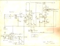
Amp is finished and I have attached a schematic. I originally had the 10K feedback resistor connected directly to the 6SF5 cathode with a 1.5K cathode resistor to ground with no bypass capacitor. But I was not getting enough gain. So I made the change you see. This gives me plenty of gain and sounds good. I could probably add a little more feedback just based on listening tests. What do you think?
Attachments
If it sounds OK to you then that is what is required. The measured voltages look in the right ballpark.What do you think?
Without any test equipment like a scope & audio oscillator it is difficult to do much more. 👍
I don't have any test equipment other than multimeters so gotta go by how it sounds. Too much sizzle is the best way I can describe it now that i've listened for a while. Going to experiment today starting with 8K feedback resistors. I prefer a warm, smooth sounding amp especially since I have Klipsch Forte speakers which can get aggressive real fast if things aren't just so.
Last edited:
- Home
- Amplifiers
- Tubes / Valves
- 6SF5 Driving 6V6 SE