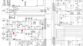
Friends, who can tell me what caused such a wild shunting of the amplifier for the German market? Are these such requirements? Or is it a "correction" for German hearing? Look at the diagram, IMHO, the removal of a heap of containers (indicated by the letter G in the diagram) should have a positive effect on the sound. Any opinions?
Attachments
These are caused by the rather extreme "FTZ" (Fernmeldetechnisches Zentralamt) regulations in Germany in the 80ties to prevent radio interference. This, for example, led to way to high input capacitances on the phono inputs. They certainly filtered out radio frequencies but parts of your music as well.

I thought so. In short, can these chains be safely deleted?Это вызвано довольно жесткими правилами "FTZ" (Fernmeldetechnisches Zentralamt), принятыми в Германии в 80-х годах для предотвращения радиопомех. Это, например, привело к увеличению входной емкости фоновых входов. Они, безусловно, отфильтровывали радиочастоты, но также и фрагменты вашей музыки.
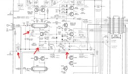
In picture 2 there is C308 which can be changed from 100p (G) to 47p (UK,AEP), all others you have marked, yes, they could simply be removed. This would revert the "G" (Germany) model to the original "AEP" (Asia/Europe/Pacific) model.
Yes, I understand. Thanks!In picture 2 there is C308 which can be changed from 100p (G) to 47p (UK,AEP), all others you have marked, yes, they could simply be removed. This would revert the "G" (Germany) model to the original "AEP" (Asia/Europe/Pacific) model.
Though FTZ was a tad too much some of those caps better stay there (like C102, C103, C425). Today RF is all around you and the caps might be the exact right solution for that.
RC filtering is a blessing and not a curse but better use film capacitors and not ceramic ones. At amplifier inputs calculate for 100....150 kHz cutting frequency.
RC filtering is a blessing and not a curse but better use film capacitors and not ceramic ones. At amplifier inputs calculate for 100....150 kHz cutting frequency.
Last edited:
These capacitors are of the pF order and have no effect on the sound. This is some psychosis with these capacitors basically connecting the housing with the ground of the amplifier.
Firstly, they protect against excitation of the amplifier at high frequencies.
Secondly, in 30-year-old devices, NIpoon Chemi-Con AVF series capacitors dry out, they can cause changes in the sound, certainly not 100pF ceramics (unless it has a short circuit, but this is unlikely to happen).
Sony often develops cold solder joints after such a period of time; the lack of good contact in some parts of the circuit not only degrades the sound but may also damage the amplifier.
These capacitors should not be removed, they have no effect on the sound.
The filter cutoff frequency of 1 MHz is already beginning to affect the frequency of 20 kHz. Therefore, the cutoff frequency of 1.59 MHz is quite optimal.At amplifier inputs calculate for 100....150 kHz cutting frequency.
they protect against excitation of the amplifier at high frequencies.
I can't see or hear any excitations on the oscilloscope without these capacitors. And yes, these capacitors also affect the sound! And not for the better!they have no effect on the sound.
If they are ceramic disc type caps (which they are) then yes. Always check cutoff frequency -3dB point of the inputs RC filter being around 100 kHz and use quality film caps. Styroflex used to be good for this but MKP will also be good.
We used to remove the excess FTZ ceramic caps with a small sidecutter even in brand new amplifiers. FTZ amplifiers usually were the worst sounding versions.
The benefits of just input filtering against todays electrosmog are evident.
We used to remove the excess FTZ ceramic caps with a small sidecutter even in brand new amplifiers. FTZ amplifiers usually were the worst sounding versions.
The benefits of just input filtering against todays electrosmog are evident.
Last edited:
Ha that is good. Had a TA-F690ES very long ago when these were hot so details have faded. So you don't need to change anything in the input filtering. You can do the cell phone test.
I do recall the driver transistors to become too hot and needing heatsinks.
Anyway you have learned what FTZ is and their effect. It was quite exaggerated in a time when no cell phones existed. Today we have smart transmitters, bluetooth, wireless and whatnot and many don't use input filtering....
I do recall the driver transistors to become too hot and needing heatsinks.
Anyway you have learned what FTZ is and their effect. It was quite exaggerated in a time when no cell phones existed. Today we have smart transmitters, bluetooth, wireless and whatnot and many don't use input filtering....
😉I do recall the driver transistors to become too hot and needing heatsinks.
Attachments
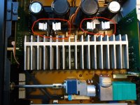
Those are huge. Not too heavy for the Pertinax PCB? I have had Sony amplifiers where the PCB tracks had come loose because of the heat. Quite weak PCB material too.
I tried the other Sony's after that. Especially the TA-FA3ES was a good one. It was even hotter than the older ones 🙂 Still have a TA-S7 which was not too good, I rebuilt one from 3 examples. The "bridging" of PCBs with those white connectors caused many errors/defects.
One of the very best of that time was the Akai AM-U5 open loop amplifier but it had an error-prone volume controller.
Last edited:
One of the very best of that time was the Akai AM-U5 open loop amplifier but it had an error-prone volume controller.
Thanks for mentioning this.
In '84 i was rather shocked from the sound of this amp driving Akai SW30 speakers. It wasn't a pleasant experience as i had a much more "sophisticated" and better specced system at the time and was rather humbled to hear a high thd amp into single driver speakers sound so much better.
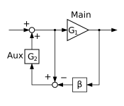
Not really open loop but the application of nfb is rather unusual. Don't recall this circuit ever been discussed here.
It sure needed a small modification. Just 4 extra caps over 4 resistors I recall. Funny thing was that it sonically outperformed the much more expensive competitors then.
It was an open loop amplifier with Hawskford error correction wasn't it? Anyway it was rather unique together with the slightly less good performing AM-U7 (just higher voltage rails, otherwise identical). After that one things went back to "normal".
I scrapped various of them when the unusually large sliding volume control went bad (as usual). There appeared no alternative when stock was depleted. Also the JFET voltage regulators in them usually were way too hot. Always shocking results when measuring as the heatsinks were energized with +/- 70V! The heat could be lessened by disconnecting the phono part ("who needs that now CD is around?"). I am surprised some still turn up now and then.
1984... and being fully DC coupled (NO coupling caps), having a speaker protection relay and a DC servo both in phono and in power amplifier.....
Attachments
Last edited:
+1One of the very best of that time was the Akai AM-U5 open loop amplifier but it had an error-prone volume controller.
Some very good amps unfairly snubbed by Akai and JVC.
- Home
- Amplifiers
- Solid State
- Sony TA-F590ES for Germany