Hello,
I'm planning to upgrade the power supply of my subwoofer amp. Long story short, i made a mistake by purchasing the wrong kind of psu and now i ended up with selectable output voltage (25v/35v/45v) dual rail halfbridge smps that i can't return.
It's working without a problem, but just using/loading one of the two rail makes me uncomfortable.
The last time i use/load one of dual something like class d amp (using one of the two channel of tpa3116d2) ended up on blown amp and burnt speaker.
btw, i use tda7498e class d amp wich requires single rail supply, 36v is the upper limit.
I have a plan on how am i going to do this, i also (i think) already have reverse engineered it, but i'm not quite sure yet.
so, here's the smps.

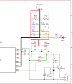
and this is the schematic of the smps that i reverse engineered and drawn on easyeda.

Before i proceed with my plan, i need an input on the schematic.
is it right/correct? is there anything that i got it wrong?
Thanks.
ps: sorry if my english is bad, since it's not my first language.
I'm planning to upgrade the power supply of my subwoofer amp. Long story short, i made a mistake by purchasing the wrong kind of psu and now i ended up with selectable output voltage (25v/35v/45v) dual rail halfbridge smps that i can't return.
It's working without a problem, but just using/loading one of the two rail makes me uncomfortable.
The last time i use/load one of dual something like class d amp (using one of the two channel of tpa3116d2) ended up on blown amp and burnt speaker.
btw, i use tda7498e class d amp wich requires single rail supply, 36v is the upper limit.
I have a plan on how am i going to do this, i also (i think) already have reverse engineered it, but i'm not quite sure yet.
so, here's the smps.
and this is the schematic of the smps that i reverse engineered and drawn on easyeda.
Before i proceed with my plan, i need an input on the schematic.
is it right/correct? is there anything that i got it wrong?
Thanks.
ps: sorry if my english is bad, since it's not my first language.
Last edited:
@greenocean
I already done the conversion from dual to single rail, it's not like what you suggested to me.
What I did was:
1. split the secondary winding center-tap, so now I have 2 windings.
2. put a bridge rectifier at each of the winding, 4 diodes per winding, so that's 8 diodes.
3. paralleled the output of the bridge rectifier and the reservoir capacitor.
I know with this setup the diode loss is doubled, but the current capabilities are increased because the previous setup and/or your suggested setup just utilizing 2 opposed phase half-wave that become a 1 full-wave.
The current setup utilize 4 half-wave, 2 of them are opposed phase, and the output is 2 full-wave paralleled, in theory this should increase current capabilities, at most double the current.
Now it runs cooler, previously the transformer temp is not that hot, warm to the touch, now, ice cold. And the voltage drop from diode loss isn't that bad either, it's just down .5v.
thanks for the reply though, I appreciate it.