D
Deleted member 543346
Hi.
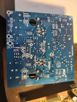
Got a pair of monoblocks from Advom that had issues when i bought them , and after some research i found that the main reason they fail is due to leaky capacitors on input board.
I opted to order new boards fom Hoppes with matched transistors , and then built / populated the rest on my own.
First amp had an offset of - 166mv , and after some reading on hoppes brain notification notes i found that the input board i built was working as intended.
Dc servo was well within specs along with pin 3 and 4 , so the issue was likely to be downstream.
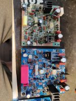
Took out the output assembly where i checked all components , and only found 2 resistors to be drifted slightly....one that was 8.5 ohm (should be 7.5ohm) , and one that was 66 ohm (should be 68 ohm).
Changed the 2 resistors , cleaned it up and put it together...worked perfectly now with dc offset around single digits millivolts 🧐.
Did not really feel i found the issue on that 🤷
On the next monoblock i powered up slowly with dimbulb / variac (did same on first monoblock) , and had dmm on testpins looking for bias current and dc offset as i increased.
Seeing bias current but also alot more dc offset than the first amp.
Tried with full current on dimbulb to see how mutch offset , and it was - 3.2v.
Pin 3 and pin 4 on input board show correct voltages along with dc servo current.
Took apart the output assembly on this amp aswell ,.and found 2 resistors (same as first amp) to be slightly off and changed them.
Seem one or more of the output transistors is weaker than specs suggest (2sd424) , having hfe in the thirtys (hfe 34).
Could some weaker transistors be the reason of the offset i am seeing?
Datasheet say minimum hfe of 40
Got a pair of monoblocks from Advom that had issues when i bought them , and after some research i found that the main reason they fail is due to leaky capacitors on input board.
I opted to order new boards fom Hoppes with matched transistors , and then built / populated the rest on my own.
First amp had an offset of - 166mv , and after some reading on hoppes brain notification notes i found that the input board i built was working as intended.
Dc servo was well within specs along with pin 3 and 4 , so the issue was likely to be downstream.
Took out the output assembly where i checked all components , and only found 2 resistors to be drifted slightly....one that was 8.5 ohm (should be 7.5ohm) , and one that was 66 ohm (should be 68 ohm).
Changed the 2 resistors , cleaned it up and put it together...worked perfectly now with dc offset around single digits millivolts 🧐.
Did not really feel i found the issue on that 🤷
On the next monoblock i powered up slowly with dimbulb / variac (did same on first monoblock) , and had dmm on testpins looking for bias current and dc offset as i increased.
Seeing bias current but also alot more dc offset than the first amp.
Tried with full current on dimbulb to see how mutch offset , and it was - 3.2v.
Pin 3 and pin 4 on input board show correct voltages along with dc servo current.
Took apart the output assembly on this amp aswell ,.and found 2 resistors (same as first amp) to be slightly off and changed them.
Seem one or more of the output transistors is weaker than specs suggest (2sd424) , having hfe in the thirtys (hfe 34).
Could some weaker transistors be the reason of the offset i am seeing?
Datasheet say minimum hfe of 40
Attachments
D
Deleted member 543346
D
Deleted member 543346
The Hopps boards are rebuilds, so the attached service is an accurate reference?
It's unlikely low beta would be responsible for output error of a few Volts. Is the -3.2V voltage you mention above in the first post the servo output voltage, or output voltage of the power amp?
If -3.2V at PA output, on IC101, would you measure supply rail voltages, and IC101 pin 6, base Q101, base Q105, and output voltage.

D
Deleted member 543346
D
Deleted member 543346
Update:
Both amps is now working. Sub 5 mv offset on both amps.
Culprit of negative dc voltage on second amp was a faulty capacitor that has been added in the positive terminal by someone before me.
Now the last issue is speaker pop while power on and power off , and i belive the main reason is due to mismatched outputs.
Any pointers to speaker relay circuit i could add here?
D
Deleted member 543346
Still not been able to find the reason for theese loud pops when turn on/off.
One of the old input boards was working and had the same pops as theese new ones.
One of the old input boards was working and had the same pops as theese new ones.
- Home
- Amplifiers
- Solid State
- Adcom GFA-565 rebuild / upgrade issue