Hi everyone.
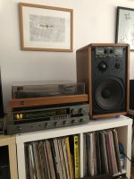
Last time I bought quite decent vintage speakers produced in 1979. They are Kirksaeter Monitor 120. Incredibly good condition looking on their age. Nearly no marks of wear on boxes, all working. Really good, balanced sound and not bad bass taking into consideration boxes are small - as usual for monitors. People from AudioKarma say they are remarkably good speakers. But... they are old, that means recapping is a must, recabling also. And the problem begins - I have searched through internet for any info about technical matters and found nothing but technical data. Maybe some of members took such Kirksaeters on workshop and recapped them? Any other forum has no info about that. Any advice highly appreciated. Here are pics of speakers and their crossover.


Last time I bought quite decent vintage speakers produced in 1979. They are Kirksaeter Monitor 120. Incredibly good condition looking on their age. Nearly no marks of wear on boxes, all working. Really good, balanced sound and not bad bass taking into consideration boxes are small - as usual for monitors. People from AudioKarma say they are remarkably good speakers. But... they are old, that means recapping is a must, recabling also. And the problem begins - I have searched through internet for any info about technical matters and found nothing but technical data. Maybe some of members took such Kirksaeters on workshop and recapped them? Any other forum has no info about that. Any advice highly appreciated. Here are pics of speakers and their crossover.
That looks like a modified X-over to me…
Recapping probably isn’t even that necessary. The yellow and small white bricks are foil type capacitors and the two bipolar capacitors don’t seem to be that old. But would try and check if they are even close to original.
Recapping probably isn’t even that necessary. The yellow and small white bricks are foil type capacitors and the two bipolar capacitors don’t seem to be that old. But would try and check if they are even close to original.
I have to buy decent LCR meter do do all necessary measurements. But last night I had some luck contacting guy from Germany. He has identical speakers and shared some thoughts with me, giving also caps data. First of all that beuatiful "tree" of capacitors seems to be made around 2000-2005, as those days 15uF 160V caps were in fact impossible to get. Even now there are not too many offers of MKP or MKT caps of such value. So - caps are nearly 20 years old and rather need replacement - but real values need to be measured. But more interesting is that even having the same speakers we have differences in coils inductance in mid/high ranges. His coils are 0,15/1,25/0,10mH. Mine - 0,20/1,60/0,20mH. None of us knows, which are proper, but most probably his mids/higs are more pronounced than mine. I want to replace also coils, so they need also to be measured - inductance and resistance. I was advised, that choosing for bass a coil with a lower resistance than original can improve bass action a little, so I will go for it. Rest of coils should be choosen according to exact measure, as mid/higs coils resistance can be a part of crossover setup calculaction. Anyway - they are not expensive, so maybe I will experiment.
BTW - two smallest white bricks close to top edge of crossover are cement resistors, not capacitors.
For anybody, who will find that post useful and have Kirkseater Monitor 120, here are caps values:
Foil 4,7uF 100V (lower edge in the middle) - Jantzen Cross Cap MKP or Jantzen MKT can be used
Bipolar electrolytic 15uF 160V (in center of crossover) - Jantzen MKT can be used
Bipolar electrolytic 100uF 35VDC(!) (lower edge right) - Mundorf E Cap50 can be used
That is of course rather budget solution. I see no sense to put there Jantzen Audio Alumen or
Maybe that post is not very electronically DIY 😉, but still something to make. I have started to strip old, ugly lacquered surface to see, what's underneath and if speakers need veneering. And voila! Those speakers have solid walnut wood cabinets! Really nice - no need to make anything more than polish with 180, 240, 360 sand paper, oil and wax...
Before

After

LCR meter bought, this weekend I will rip out all electronics to measure and check for replacement.
Before
After
LCR meter bought, this weekend I will rip out all electronics to measure and check for replacement.
So, all measures are now done. And there are differences between nominal and real data, as follows:
Capacitors
"tree" in the middle - nominal 14,7uF (4,7 +10), real 20uF (5 +15) (without resistor, of course)
big bipolar capacitor - nominal 100uF, real 200uF (too big leakage for sure)
Coils
Big one for bass - nominal 2.0mH, real 2.0mH 0.25 ohm
Middle size one - nominal 1.5mH, real 1.6mH 1.35 ohm
Small ones - nominal 0.20mH, real 0.23mH 0.42 ohm
Capacitors should be replaced for sure. Mid and high tones coils will be replaced with nominal values. Now I am curious, how to deal with bass coil to give speakers some more punch, or just a little more dynamic. Should I lower a little the inductance - let's say to 1.80mH or rather leave 2.00mH as it is and lower resistance from 0.25 to 0.15 ohm? I know, that this is complicated subject as speaker Qts can .lower, but I can deal with it changing amount of internal damping.
Last edited:
@Sir_Gorg Great catch man & greetings from Serbia! I'm a fellow Kirksaeter enthusiast so please do report on your findings. I've got the same speakers and the Kirksaeter Moderator 100C, so I'm looking to recap both. Mine are in a very good cosmetic and sonic condition, but I would love to "reset" them to their factory glory and thus secure them for the years to come.
Attachments

If made in -79 as stated, remember that that these are now 44 year old speakers.
As Markbakk points out, I doubt that these were "hi-precision" filters in the first place (if they were I would not expect the rheostats for mid and tweeter lever adjustment for one. The speaker element will likely have changed characteristics with time, magnetic fluid dried out etc.
Shure - go ahead and change out the older out of spec electrolytics with devices in spec. To my mind it should be no reason to go overboard, any polyester, MKT, MKP etc capacitors will be better than the electrolytics ever was anyway.
No reason to expect that coils change inductance over time. Both 15uF and 100uF should be easy enough to get.
As for the inductor - don't change the value, You could opt of a lower DCR value but to be honest I don't see the point.
Assuming these are sealed boxes(?) I would rather consider checking the speaker Q and if lower than approx 0,7 I would reduce the internal volume to acheive a Q of about 0,8 for more percived "punch" in the base. In the past I have putt old pocket-books inside the cabinet just for evaluating/testing the effect of a smaller box volume.
Remember that back in -79, Sinclair had yet to market his ZX-80 computers. Voltmeters were analog with needles and speaker measurements were made in anechoic chambers using B&K microphones.
What is today common knowledge amongst some DIY'ers was not even "specialist" knowledge at the time and with computers and measurement software we are likely miles ahead of what most specialists had available at the time.
This is DIY-forum. If you really want to take these speakers' potential to the max I recommend that you read up and do a full re-design based on SPL and impedance measurements rather than "component swapping"
@LJT - thank you for your valuable feedback.
I have decided to keep all inductors on the same value as found originally assembled and I will only test a smaller resistance for bass driver. Unfortunately, I have no access to any instruments letting me check speakers Q, impedance curve or SPL, so my first try will be based only on listening experience. Most probably soon I will try the trick with Dayton Audio DATS V3, but I need to buy it 😀 Well - decreasing a volume of box was one of my thoughts, so polyester fill was bought (4cm thick). In late 70's closed box were underfilled generally, what I noticed - no damping on side walls at all. Now I am waiting for delivery of coils and capacitors. First I will complete only one speaker to have possibility to compare. I hope to get first results of experimenting closest weekend.
There is one very good place for complete redesiging/upgrade of speakers where I live, unfortunately it is very expensive.
@ryekido - I will report effects of tune for sure.
Hi again. Managed to assemble measuring mic (Panasonic WM61), got calibration file. I have tried to make measurements in REW and HolmImpulse. I see a long way to learn in that discipline, as I hardly understand some operations of both programs - for example combining of graphs from 1m and near field measurements 🙁 Still reading a lot of instructions all over different forums, but those differ depending on program version - especially REW.
Telling the truth, now I think, whole crossover should be redeisgned to get better response? Do not bother with raise in high tones - WM61 mic has +6dB raise on highs, which was not fully cleared even with mic calibration file.
Measuring condition far from laboratory - just ordinary room, but side obstacles 2,5m far from axis, floor covered with damping materials to reduce reflections.
REW measures

REW aligned sum with phase

I suppose, that extra jumps or "steps" in phase in two places (around 200Hz and 2kHz) can be caused by attenuators and fuses on all drivers. I will try to replace fuses with copper jumpers and make measures again.
HolmImpulse measures
RED - 1m SPL measure at 75dB
GREEN - near field SPL bass driver measure at 75dB

Easy to see, bass driver response much differs between programs from beginning up to around 80Hz...
What do you think about those data?
Telling the truth, now I think, whole crossover should be redeisgned to get better response? Do not bother with raise in high tones - WM61 mic has +6dB raise on highs, which was not fully cleared even with mic calibration file.
Measuring condition far from laboratory - just ordinary room, but side obstacles 2,5m far from axis, floor covered with damping materials to reduce reflections.
REW measures
REW aligned sum with phase
I suppose, that extra jumps or "steps" in phase in two places (around 200Hz and 2kHz) can be caused by attenuators and fuses on all drivers. I will try to replace fuses with copper jumpers and make measures again.
HolmImpulse measures
RED - 1m SPL measure at 75dB
GREEN - near field SPL bass driver measure at 75dB
Easy to see, bass driver response much differs between programs from beginning up to around 80Hz...
What do you think about those data?
Measure at 1m and apply a time window on the impulse response (aka ‘gate’). That way you exclude reflections.
In general, a rising curve like this sounds way to bright. The difference between 300Hz and 12kHz is over 10dB. So you do need to do some tuning. But first get your measurements right.
In general, a rising curve like this sounds way to bright. The difference between 300Hz and 12kHz is over 10dB. So you do need to do some tuning. But first get your measurements right.
Well. In general it is normal behaviour of those speakers - they are very bright. And mic adds around 3dB on highs. What comes to gating - I did not add any, because when I looked on impulse respones, there were... no reflections in bass range. At all. I am curious, if a huge impact on graphs is not caused by... amplifier. To emit test signal I am using tube amp, so the sound may very depending on used tubes.
Hi,
first, changing the electrolitics is a good idea, but change the 10uF for a film capacitor. The foil capacitors do not age at all. No need to go 160V. Even 50V will do. Electrolitics get dry, not even changing their value when measured. They can/ will induce distortion when aged. The 100uF is not in the signal chain and only for bass. Not critical, no need to go film cap.
Changing coils is 100% no-sense, as they do not age.
If you change the bass coil, which is already very low resistance, for an even lower Ohm part, you will actually loose bass, not get more.
You can proof this in a simulation of a closed box, maybe in winISD. Changing the resistance by .25 Ohm will not even be noticable in the diagram.
As it is a bell type coil with .25 Ohm, even if you get a 12lbs zero Ohm coill, it will hardly be measurable and not audible.
This may disapoint you, as you can only spend around 10-20BP/$/€ on the pair, but be assured, this is the best you can do to these speakers.
Maybe change the inside wires to the speakers, as the copper can corrode/ get black inside the insulation. Fit some convenient binding post on the back.
Have a look at the damping material used. Best is mineral wool (Rockwool), even if it is cheap. Cleaned, fat free Sheep's wool is not better or worse, if you prefer organic and expensive.
They used all kinds of funny materials at that time, like foam or rags. You can improve a little if you do not find this yellow Rockwool stuff inside and maybe get a small improvement in the low range. The inside has to be completely filled, but not or just a very little, compressed.
Good luck!
Thank you for suggestions. In a meanwhile I have made measurements again, this time properly gating them - previously shown graphs did not show true as they were wrongly prepared for reading (I really did not know how to read reflections). And as I see, my work gave noticeable effect. Made - box walls damped with bitumen pads, whole box filled with polyester wool (250 grams), all cables replaced to oxygen free copper, crossover recapped, speaker terminals changed, all sealing new (full seal now, boxes were not sealed before), fuses replaced to solid copper connection (I do not afraid of that, as it is impossible to blow speakers with my amp, it is too weak).
Here is a final measurement.
Red - modded
Green - unmodded

Here is a final measurement.
Red - modded
Green - unmodded
This looks quite good. I hope you like the sound. These where very capable speakers at their time. They should sound quite pleasant, with a todays amp and signal sources. Good move to replace the fuses!
Have fun!
Have fun!
Looks good. But know that virtually any amp can blow virtually any tweeter. Just drive it to clipping levels, you'd be surprised how even a small amp can burn those voicecoils.
Todays amps are less critical than in the 70s. A million tweeter survived without fuse. As these are working 4500Hz up, it should be a very small risk.
Anyway, this seemed to be more of a "pro monitor" feature, to make them look more technical.
Anyway, this seemed to be more of a "pro monitor" feature, to make them look more technical.

A fuse isn’t necessary. Some care with output levels is. Most class AB amps I know of don’t have a lot of protection against output signals trying to exceed supply voltage levels.
In the old days high powered amps were very expensive. A real 50W rms/8 Ohm amp was a high power dream for most. So if you had a typical middle class, 25 W AB transistor amp, it was quite easy to drive it into hard clipping, just listening a little bit louder, not to mention a party. Clipping was audible long before power compression happened. Today you get a wonderfull, real 2x150W RMS amp for less than 100US$. You don't drive such amps into clipping if you are still half sane. Also, if you try and have a well made vintage speaker, you may notice a point where more power doesn't mean any louder sound. Quite funny.
Fact is, strong amps don't kill speaker, weak ones do. These weak 70s amps are long gone, as most of them sounded "special" to say it polite. Not all vintage gear was worth keeping if we are honest.
Fact is, strong amps don't kill speaker, weak ones do. These weak 70s amps are long gone, as most of them sounded "special" to say it polite. Not all vintage gear was worth keeping if we are honest.
- Home
- Loudspeakers
- Multi-Way
- Kirksaeter Monitor 120