Is anyone able to decipher this jumper diagram for a Broskie Aikido amplifier?
I have built the board with 6.3v DC H+ and installed jumpers J8, J5, J9 and J3 to wire the heaters in parallel exactly as John Broskie suggests. However, only valves V3 and V4 are lighting up.
Can anyone with a sharper eye determine if the instructions are incorrect or incomplete?

I have built the board with 6.3v DC H+ and installed jumpers J8, J5, J9 and J3 to wire the heaters in parallel exactly as John Broskie suggests. However, only valves V3 and V4 are lighting up.
Can anyone with a sharper eye determine if the instructions are incorrect or incomplete?


Thx all - much appreciated.
I've built his stuff before and the guides frequently have errors so thought it safest to check here first!
I've built his stuff before and the guides frequently have errors so thought it safest to check here first!
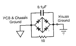
On another note (also unclear in the manual) - if there are separate B+ and H+ supplies, should both of the negatives be taken to the center/star ground on the PCB (which also joins to the chassis?).
I currently have two DC socket terminals, one for the heaters (6.3v DC H+) the other for the plates (24v DC B+). Either or both could be grounded in the chassis but I would add that they both have separate earth pins in their external PSU cases anyway.
I currently have two DC socket terminals, one for the heaters (6.3v DC H+) the other for the plates (24v DC B+). Either or both could be grounded in the chassis but I would add that they both have separate earth pins in their external PSU cases anyway.
Re the jumpers, for anyone reading this in the future - it needed J10, J11 and J12 as additional to Broskie's instructions (J5, J8, J9 and J3).
With only J10 and J12 added, the heater on V2 failed to light. Adding J11 fixed this.
So the final solution for using a separate heater power supply for parallel wiring is J3, J5, J8, J9, J10, J11 and J12.
With only J10 and J12 added, the heater on V2 failed to light. Adding J11 fixed this.
So the final solution for using a separate heater power supply for parallel wiring is J3, J5, J8, J9, J10, J11 and J12.
Curious. Maybe bad board trace connection to J10? Also wonder if it's the kind of thing the vendor would appreciate being told about.
Yes I'll drop John Broskie a note, although I've emailed him a few times but he does seem to be very busy.
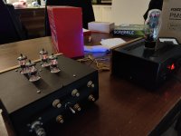
All seems to be working fine, just completed the test drive.
Bit of an odd box of old components to pull it together but it may well be one of the only 5U4G rectified 6GM8 amplifiers ever made. Had the parts so thought why not drop the voltage out of the rectifier down to 24v 😂
All seems to be working fine, just completed the test drive.
Bit of an odd box of old components to pull it together but it may well be one of the only 5U4G rectified 6GM8 amplifiers ever made. Had the parts so thought why not drop the voltage out of the rectifier down to 24v 😂
Attachments
- Home
- Amplifiers
- Tubes / Valves
- Heater diagram interpretation - Broskie