All,
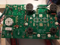
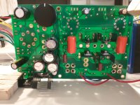
I'm currently building a TSE-ii for 300b tubes. I'm using the Hammond 276X power transformer, and, at least at the start, the big edcor 5k OPTs. Pictures of the board below. I have the capacitors and transistors mounted on the bottom of the board, and the resistors on top.
I started the checkout procedure today, and the plate voltage on V2 (one of 5872's) is way off - it's currently up around 272 vdc. FWIW, the plate voltage on V1 is fine - I can set it to 175 vdc using the trim pots.
I'm not sure why the plate voltage on one driver tube is so high. I'm also concerned that the B+ might be too low. I'd be grateful for any thoughts and/or suggestions.
Here are some readings:
Also, is that B+ too low? I took C1 out of the board, per the note #1 in the BOM notes.
Pictures from my build are attached. Thank you in advance for any help! Let me know if you need any other info or measurements.
Dan
I'm currently building a TSE-ii for 300b tubes. I'm using the Hammond 276X power transformer, and, at least at the start, the big edcor 5k OPTs. Pictures of the board below. I have the capacitors and transistors mounted on the bottom of the board, and the resistors on top.
I started the checkout procedure today, and the plate voltage on V2 (one of 5872's) is way off - it's currently up around 272 vdc. FWIW, the plate voltage on V1 is fine - I can set it to 175 vdc using the trim pots.
I'm not sure why the plate voltage on one driver tube is so high. I'm also concerned that the B+ might be too low. I'd be grateful for any thoughts and/or suggestions.
Here are some readings:
- With just the rectifier tube in: B+ is 350 vdc and negative bias voltage is -134 vdc
- With the rectifier and the 5872s in: B+ is 275 vdc and negative bias voltage is -108vdc
- Plate voltage on V1 can be set to 175 by turning trimpots
- Plate voltage on V2 is about 272 vdc
- I looked at the schematic and noticed that the CCS array is connected to the plate of V1 & V2, so I took some measurements on the ICs:
- For V1 (the driver tube that seems to be working ok): there are 144 vdc on the Gate, 275 vdc on the Anode, and 164 vdc on the Cathode
- For V2 (the wonky driver tube): there are 271 vdc on the Gate, 275 vdc on the Anode, and 275 vdc on the Cathode
- I looked at the schematic and noticed that the CCS array is connected to the plate of V1 & V2, so I took some measurements on the ICs:
Also, is that B+ too low? I took C1 out of the board, per the note #1 in the BOM notes.
Pictures from my build are attached. Thank you in advance for any help! Let me know if you need any other info or measurements.
Dan
Attachments
Good news (although I'm ashamed to admit it) - those measurements were off b/c I still had the dim bulb current limiter plugged in .... Sorry.
But - there is definitely something wrong w/ my amp. I took out the current limiter, and then took some measurements with the rectifier and 5782's in: B+ = 444 vdc; negative bias voltage = -178 vdc; V1 plate voltage = 175 vdc; V2 plate voltage = 175 vdc (those last two measurements after adjusting the trimpots).
So I thought that all sounded good. Power down, wait a bit, then I put in the output tubes and connected speakers. I turned it on and initially all was OK, but after maybe 5 seconds there was a flash in the rectifier tube, then nothing, then another few flashes and some thumping noises from the speakers (I think the flashes in the rectifier and the thumping noises from the speakers occurred simultaneously, but it's kind of a blur). The power transformer started smoking and actually audibly vibrating and shaking on the board. It took me a bit longer than I'd like to admit to pull the plug because of all the mayhem.
I've looked over the board and havn't found anything obviously damaged or wrong. I'd be happy to post any more pictures, if that would be helpful. I double checked my board connections, and I think everything is correct. I used the diagram from this post to determine the connections. Any thoughts on what might have gone wrong? The only other time this has happened to me (smoking a power transformer, that is) occurred when I grounded a center tap that shouldn't have been grounded (or didn't ground a center tap that needed to be grounded, I forget which now).
Last thing - after a while, I was curious, so I pulled all of the tubes out of the board, put the dim bulb limiter back in line, and then plugged the amp in. The bulb lit up super bright and stayed that way for a few seconds until I powered down. I infer this mean's there is a short in the circuit, and that it's likely to be in the power transformer. Does that sound right? I killed it?
Last last thing - would best practice for doing the checkout procedure be to reinstall the dim bulb current limiter each time you add a new tube to the circuit?
Thanks again for any help!
Dan
Sorry about these unpleasant events. I’m not expert on the TSE-II since my PCB sits untouched in the closet, but since none of the experts replied yet, I will try and think with you and hopefully figure it out.
Let me first ask:
1. The driver stage and voltages were fine until you put in the power tubes. Is this correct?
2. I did not see that you posted measurements for your heater voltage on the power tubes. Since you did not place C1 I assume you are using 300Bs? Did you measure the correct heater voltage?
3. Before inserting the power tubes did you krank up the bias for maximum negative value? This will bias the output tubes into cut-off so that virtually no current should flow through the power tubes (except the heaters of course).
4. Sounds as if both power tubes were inserted simultaneously before turn-on and the trouble started. Or did you do one at a time?
5. I assume you installed a fuse from the power line-in before the power transformer primary? If that did not blow hopefully the current was not high enough to damage the transformer.
However, based on your final dim-bulb test without any tubes (no rectifier, right?) it does sound if the power transformer was damaged. But the, why did the fuse not protect it? What amperage of fuse did you use? You may want to measure resistance (continuity) for the various windings in your transformer. You may also check resistance/continuity on you output transformers, just to be sure.
After we have answers to the questions above we will have a better idea what caused the problem/short when you inserted the power tubes.
Good luck.
Thanks, Francois. I appreciate your post. Indeed, I am building a 300b amp.
I just removed the PT connections from the board, and connected the primary side to the wall voltage. Within about 15-20 seconds there was a lot of smoke pouring out of the transformer so I shut it down. So that's with no connections on the secondary side. I take that to mean the transformer is as they say forked, right?
Again, thanks for the questions. Please let me know if you have any more or if there's other information I can provide.
Best,
Dan
- Yes, things looked good while following the checkout procedure up until I put in the output tubes (I did put both in at once).
- The heater voltages for the output tubes were both very very close to 5.0 vdc. I think they were both 5.02 vdc, or something like that.
- I don't remember the filament voltages for the 5782s exactly, but they were near 6.3 vdc, I believe.
- I did set the bias to the maximal negative value, as per the checkout procedure. I don't remember what value that was,... Thank you for explaining the rationale behind this.
- Yes, both tubes inserted one at a time. I can see that, next time, would be better to do one than the other.
- Yes, I had the power cord fused. It was a 10A fuse. Is that way too high?
- The PT I'm using (Hammond 276X is specified for 5A on the 6.3v secondary, 3A on the 5V secondary, and 172ma on the HV secondary.
I just removed the PT connections from the board, and connected the primary side to the wall voltage. Within about 15-20 seconds there was a lot of smoke pouring out of the transformer so I shut it down. So that's with no connections on the secondary side. I take that to mean the transformer is as they say forked, right?
Again, thanks for the questions. Please let me know if you have any more or if there's other information I can provide.
Best,
Dan
Last edited:
I'm not familiar with the board, but one obvious thing to check first is the orientation of the 300B sockets, if flipped or offset the events you described would be very likely.
A bit more info -- Here are some readings from the amp with the rectifier and driver tubes installed (no output tubes).
B+ = 440vdc
Negative Bias Voltage = -178vac
pin 1 of 5872s = 175vdc (that's on each driver tube, after setting via the trimpots)
Thanks again for all of your help!
Dan
B+ = 440vdc
Negative Bias Voltage = -178vac
pin 1 of 5872s = 175vdc (that's on each driver tube, after setting via the trimpots)
Thanks again for all of your help!
Dan
Thanks, Kevin. I did measure the heater voltage on pins 1 & 4, so I don't think the sockets are inserted incorrectly. Also, the pin numbers on the sockets match the pin numbers on the boards.I'm not familiar with the board, but one obvious thing to check first is the orientation of the 300B sockets, if flipped or offset the events you described would be very likely.
Best,
Dan
Unfortunately it sounds as if that 276X had its moment of glory. Sorry. A fuse of 10 amps is too much for this amplifier. A better choice would be around 3 amps, and might have saved your transformer.I just removed the PT connections from the board, and connected the primary side to the wall voltage. Within about 15-20 seconds there was a lot of smoke pouring out of the transformer so I shut it down. So that's with no connections on the secondary side. I take that to mean the transformer is as they say forked, right?
The possible fault scenarios as I see them are:
1. Was there a problem on the primary-side wiring
2. Was the transformer defective to begin with.
3. Was there some other issue that caused a short to ground when you inserted the 300bs
4. Was one of the 300b tubes defective and shorted. (Do you have a tester to check the tubes?)
Before going further, is it possible to check which windings failed in the power transformer secondaries? Continuity check and resistance for each winding. And check the output tubes if possible.
Hi Francois,
thanks again for following up. I've ordered a replacement 276x power transformer. I will proceed more methodically (and use the correct valued fuse!) when it arrives.
Some responses to your questions:
Secondary:
HV1 - HV2: 112.7 Ohms
HV1 - HVCT: 60.3 Ohms
HV2 - HVCT: 52.8 Ohms
6.3V_1 - 6.3V_2: 0.3 Ohms
6.3V_1 - 6.3CT: 0.3 Ohms
6.3V_2 - 6.3CT: 0.2 Ohms
5V_1 - 5V_2: 0.3 Ohms
5V_1 - 5VCT: 0.3 Ohms
5V_2 - 5VCT: 0.3 Ohms
Primary:
Black - White: 1.7 Ohms
Grey - White: 1.5 Ohms
Black - Grey: 0.5 Ohms
Probes together: 0.1
Also, I checked resistances of all wires to any other wires (e.g. HV1 to 6.3V_2, 5VCT - Black, etc.) and didn't find anything. All resistance measurements were greater than the meter can read.
Again, thanks for all of your help!
Dan
thanks again for following up. I've ordered a replacement 276x power transformer. I will proceed more methodically (and use the correct valued fuse!) when it arrives.
Some responses to your questions:
- I don't see any issue w/ the primary side wiring. I did the black wire on the transformer to fused hot, white wire from transformer to neutral. Nothing from the primary side touched anything from the 2ndary side, and nothing on the primary side was grounded (grey wire just unconnected and out of the way. Is there anything else that could have been wrong here?
- I don't know if the transformer was defective, but I did get good readings out of it before putting in the output tubes
- I'm not sure if there's some other short. I'll follow through the schematic to check continuity and resistances, etc. But is there any other good methodical way to check for shorts?
- I don't have a tube tester. The 300b tubes were purchased on Ebay, and they were listed as functioning, and the seller's reputation was very good. But ???
Secondary:
HV1 - HV2: 112.7 Ohms
HV1 - HVCT: 60.3 Ohms
HV2 - HVCT: 52.8 Ohms
6.3V_1 - 6.3V_2: 0.3 Ohms
6.3V_1 - 6.3CT: 0.3 Ohms
6.3V_2 - 6.3CT: 0.2 Ohms
5V_1 - 5V_2: 0.3 Ohms
5V_1 - 5VCT: 0.3 Ohms
5V_2 - 5VCT: 0.3 Ohms
Primary:
Black - White: 1.7 Ohms
Grey - White: 1.5 Ohms
Black - Grey: 0.5 Ohms
Probes together: 0.1
Also, I checked resistances of all wires to any other wires (e.g. HV1 to 6.3V_2, 5VCT - Black, etc.) and didn't find anything. All resistance measurements were greater than the meter can read.
Again, thanks for all of your help!
Dan
EDIT: Your post arrived while I was typing below. I will read and respond in a following message.
————-
Scenario 1: Unlikely since it worked fine before power tube insertion caused the failure. The fuse was wrong amperage but that did not cause the problem, it only didn’t prevent catastrophic failure.
2: Unlikely, but possible.
3: A “catch-all” scenario, but after a look at the schematic I still don’t have a good theory to explain what you experienced. Have you rechecked orientation (polarity) of you capacitors. Do C1, 12 & 13 look healthy now? If it is the 6.3 V winding that failed it may be a case where the minimal draw of the driver tube were handled in spite of an error, but when the 300b’s filament draws were added it burned up the winding.
4: Defective 300b possible, but unlikely to runaway if you have adjusted the tube into cutoff.
You may want to double check if you have not accidentally adjusted the bias the other way for maximum current. But then you would have most likely noticed the plate glow. If the HV winding on the transformer burned through the scenario might deserve further thought.
.
From your resistance measurement it appears that all the windings of the 276X transformer have continuity, at least when not loaded. The fact that is smokes when energized, I believe, means that the insulation on some winding(s) were compromised. It would be helpful to know which windings while trying to figure out what caused the situation. Because before installing the new transformer you need to find the cause and correct it.
Right now I can’t think of any further suggestions to offer. I hope George will see the thread and chip in.
Right now I can’t think of any further suggestions to offer. I hope George will see the thread and chip in.
Hi everyone,
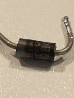
I spent some time looking over the board today. I noticed that d3 was a little... off-looking. the black cylinder w/ the grey stripe on it looks like it was damaged. It has a crack, and it generally looks kind of fried. picture attached. there's no marking on the board or anything.
My multi-meter has a diode setting. I don't really understand what the machine reads, but: when I put the COM probe to the cathode (the side w/ the stripe) and the red probe ("V_Omega_mA") to the annode, I get a reading of 218. When I flip the probes, I get a reading of 119. I'm told readings of about 500 and 0, resp., would be "good".
I grabbed a new 1000v UF4007 diode, with the COM probe attached to the cathode (w/ the stripe), I get a reading of 496. When I connect the probes 'backwards', I get the unmeasurable reading (the screen just says "1 ")
So I think that means d3 was compromised. If that's the case, does it give any hint as to a possible larger issue?
Thanks in advance for any help!
Best,
Dan
Attachments
Dan,
What schematic and BOM did you use? It might help to post them so that we can be sure we use the correct component designations.
That diode above (D3?) is gone, but could you verify what the part number is? I thought it looks like “40” across the crack. Is it a UF4007 or 1N5401? The latter part has a 100V peak repetitive reverse voltage and will fail if it was used in the negative bias generation across the HV secondary.
I assume you used the specified UF4007 for the D3, part that failed. Hard to say why it failed. But with a 640V CT primary the maximum voltage across each leg would be 2*320*root pi = ~ 900 V, i.e. close to the max for a UF4007. (Reminder to self: Use diodes with higher safety margin when building my TSE-II).
When D3 failed (for whatever reason, for now) it caused a collapse of the negative bias supply and depending on its failure mode caused an overcurrent through the primary if D3 conducted in reverse direction, as well as causing the 300bs to conduct their maximum (due to insufficient or no bias). I think this is what cooked the transformer HV winding. The question is, what else was damaged? The related circuit components and 300bs will have to be carefully checked.
Something puzzling: With a 640V CT secondary winding and a 5AR4 rectifier I would have expected a B+ (unloaded) of ~420 Vdc. Before the problems started you measured B+ close to 450 Vdc. Is your electrical supply at the wall high, or is something else going on?
plug.
My 2-cents for now. I had hoped that Grorge would check in, but he was very busy with Radon abatement, last I heard.
Good luck.
Last edited:
I checked a schematic I have of the original TSE circuit (before TSE-II) and it specified a DSEI-12 FRED for -bias supply duty - that was a 12 Amp diode with Vrrm=1200V. The current rating is overkill, but I like the 1200 V Vrrm. Wonder why George changed it.
Other builders of the TSE-II might want to rethink those diodes across the full HV winding providing negative bias.
Other builders of the TSE-II might want to rethink those diodes across the full HV winding providing negative bias.
Hi Francois,
Thanks for the help!!! I've built a Tubelab SSE previously, and always got great help from the forum here. In addition to you all, George is such a great help and resource.
I'm building the TSE-ii amp, so I used the board, schematic, and BOM from the first post in this thread. The diode that fried is D3 in the schematic, and I used this part, which is from the BOM. FWIW - according to the datasheet, it's Vrrm is 1000v, which is the highest of the UF4001-UF4007. I looked around a little bit for a 'bigger' diode, but didn't see anything right away (also I'm not so sure of the different characteristics listed and which are important, etc.). Do you have any recommendations? Would that FRED you listed work?
I appreciate your explanation of what happened when the diode died. When you say "the related circuit components and 300b's will have to be carefully checked," this refers to D2, D3, R5, R6, C6, C7, R13/24, R12/23, R11/22, R10/21, C8/10, and R9/20, is that correct? As well as the 300b tubes, which I don't think there's much I can do to check them w/o a dedicated tube checker. FWIW - i did check the tubes visually & w/ a multimeter. They look fine to me, but I'm far from an expert. But no black spots, broken wires, etc. Also, the resistance between heater pins is 1 ohm, and the resistance between each heater pin to the grid and plate is unmeasurably high (i.e. no connection) for each tube.
Thanks again for all of your help!
Dan
Sorry for not being here much. The Radon battle has been won. It involved moving everything in my basement lab to seal all the cracks in the floor many of which were under the carpet, which was under the workbenches. This included all the workbenches that were built in place without any intentions or provisions for ever being moved. The resulting mess and cleanup will last for some time. Meanwhile I have no usable workbench space.
Due to many factors, after 18 years in business Tubelab Inc will cease operations at the end of 2023. Tubelab has lost money for the last three years and so far 2023 is even worse. I haven't figured out all the details yet but I will still be on these forums.
I have three built up TSE-II boards in a box that were built some time ago. All have UF4007's in them. The original reason for the change was the random death of the DSEI-12 FRED diodes in both the SSE and TSE boards. They usually failed during a thunderstorm or other event causing a transient on the power lines. I had one blow in my SSE when the compressor in the window AC unit cycled. They were just too sensitive to spikes.
I have never seen a UF4007 fail in a TSE, but it does run close to the max voltage spec. Perhaps a higher voltage part would offer some more voltage margin. I have used the DSA 1-18D in other builds with good results but have never tried them in a TSE-II.
Due to many factors, after 18 years in business Tubelab Inc will cease operations at the end of 2023. Tubelab has lost money for the last three years and so far 2023 is even worse. I haven't figured out all the details yet but I will still be on these forums.
I have three built up TSE-II boards in a box that were built some time ago. All have UF4007's in them. The original reason for the change was the random death of the DSEI-12 FRED diodes in both the SSE and TSE boards. They usually failed during a thunderstorm or other event causing a transient on the power lines. I had one blow in my SSE when the compressor in the window AC unit cycled. They were just too sensitive to spikes.
It likely never got this far. When one of the two diodes failed it put a half wave short across the HV secondary of the power transformer. This should have blown the line fuse which should have been 2 amps on a 120 volt build. A 10 amp fuse allowed the transformer to cook itself to death.When D3 failed (for whatever reason, for now) it caused a collapse of the negative bias supply and depending on its failure mode caused an overcurrent through the primary if D3 conducted in reverse direction, as well as causing the 300bs to conduct their maximum (due to insufficient or no bias). I think this is what cooked the transformer HV winding. The question is, what else was damaged? The related circuit components and 300bs will have to be carefully checked.
I have never seen a UF4007 fail in a TSE, but it does run close to the max voltage spec. Perhaps a higher voltage part would offer some more voltage margin. I have used the DSA 1-18D in other builds with good results but have never tried them in a TSE-II.
Thank you, George. This is helpful. Sorry to hear about the Radon situation - hope it's not going to be a problem in the future! I appreciate all of the help and information you provide here on the diyaudio forum.
OK, if I understand your explanation, then it's possible that the failed diode + wrong fuse caused the transformer to fry, and that just might be the end of it (i.e. there may not necessarily be damage or other problems to diagnose in the circuit). If that's the correct interpretation, do you think I could just replace the diode (already done), a 2 amp fuse (also done), and then attach a new power transformer (in transit) and begin the startup/checkout procedure again?
Also, a question for you and the other experienced builders here -- do you use any special/fancy anti-static procedures or tools for working w/ diodes, mosfets, transistors, etc.? I've seen people talk about anti-static mats and wristbands, others say to make sure to touch something grounded before handling transistors (I worry though that walking over to touch the nearest grounded metal thing and then walking back to the workstation would generate additional static electricity), etc. Is that stuff useful or necessary?
Thanks!!
Dan
It likely never got this far. When one of the two diodes failed it put a half wave short across the HV secondary of the power transformer. This should have blown the line fuse which should have been 2 amps on a 120 volt build. A 10 amp fuse allowed the transformer to cook itself to death.
Good to get your input, George. Glad to hear you prevailed in the Radon battle.
Hope you are right, George; that Dan’s accident only fried the HV winding. But I’m a cautions guy that wears belt and suspenders 😉 and would check some parts in this situation.
I’m not sure exactly what would happen if one diode short in a full-wave rectifier set-up. Dan found that the UF4007 conducted in both directions, i.e. shorted, not opened. So, in that failure mode my hunch is that the bias will go to zero average, but that the full positive AC peak will hit the negative side of the bias capacitors once per AC cycle, especially C6. I will be suspicious of D2,D3, R5, R6, C6, C7. Perhaps the functioning of Q1 and Q2 will also need close observation, what do you think?. Only if any of these parts experienced damage will I be concerned about the rest in the chain.
I have used BY448 diodes with 1.5 kV breakdown successfully in the past and with your concurrence I will plan use those, instead of the UF4007, in the D2, D3 positions in my TSE-II build. https://www.mouser.com/ProductDetail/Vishay-Semiconductors/BY448TR?qs=Q97emo0LRprPHwnlrexMeg==
Last edited:
Once the board is powered with a good transformer and both D2 and D3 have been replaced you should measure the voltage on the grid pin of the output tube socket with no output tubes installed. The voltage should vary from a small negative voltage to a large negative voltage as the bias pot is turned. The actual voltage readings will depend on the transformer being used and the line voltage. Both tubes should have relatively similar voltage ranges. If this checks out the parts are probably OK. I don't have a working board available to measure right now and I will be away from the lab for the next 3 to 6 days. Email and forum posting may or may not be available as I may be out of cell coverage for part or all of the time.
Hi everyone,
First, thanks for all of your help. My TSE ii w/ 300b's is now making music! (caveats below)
I got a new Hammond 276x transformer, I replaced D2 and D3, as well as R5 and C6. FYI -- R5 must have suffered because it seems to have "failed open" (i think that's how you say it) -- the resistance across it is unmeasurably high when removed from the circuit. Once that stuff was replaced, I followed the Tubelab checkout procedure and things seem to be working ok.
But I really don't understand how to measure the bias of the output tubes, and am not sure if they're set up correctly. I have a meter across R18, the 10 ohm plate load resistor (i think that's how you call it). Meaning, I clip the red probe to 1 side of R18 and the black probe to the other side. With the meter set to "200m" in the section that I think indicates DC current (i.e. it has an "A" with the same two horizontal lines under it as the dc voltages section), I get a reading of about 70. This number doesn't exactly sit still, and I can adjust it by turning the trimpot R23 (very very small adjustments of the trimpot seem to result in very large changes of the numbers). . When I turn clockwise, the value on the meter goes up and the volume increases noticeably.
Is that how you measure the bias of the output tubes? When I look online for how to use a voltmeter to measure current, everywhere says you need to break the circuit to put the meter in series w/ the resistor. But the checkout procedure clearly says clip the leads to both ends of R18, which is putting the meter in parallel w/ the resistor.
Also, FWIW, the voltage when measuring from each output tube's grid to ground is about -100Vdc with music playing. I was able to set this to about -115Vdc prior to putting in the output tubes (when the checkout instructions say to make this value as negative as possible). I assume that it's increased (towards 0) because I've adjusted R23 to get the reading of about 70 on the "200m" current setting of the multimeter.
I'd be very grateful if someone could help me clear this up, and/or point me to any helpful discussion/video on setting the bias of the output tubes for the Tubelab TSE ii or other tube amps more generally.
Thank you!
Dan
- Home
- More Vendors...
- Tubelab
- TSE-II build - voltage questions