
Reducing the bias current will reduce the range of class A operation. This would possibly cause some change of its sonic character. One shoud decide by personal preferance if this is acceptable.
Hi chip_mk
Do I need to plug R6 and R11 into 2M7 ohms to draw 600mA bias current?
2.666.666,67=47000*12/((600-0,15)*0,47)
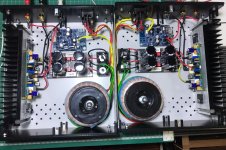
My Power Amp is working perfectly. But I have some heat problem. In one hour of operation, the coolers reach 65 C. This also makes me nervous.
I want to lower the heat a bit
Do I need to plug R6 and R11 into 2M7 ohms to draw 600mA bias current?
2.666.666,67=47000*12/((600-0,15)*0,47)
My Power Amp is working perfectly. But I have some heat problem. In one hour of operation, the coolers reach 65 C. This also makes me nervous.
I want to lower the heat a bit
Attachments
Yes, replace existing R11 and R6 (1M8) with new resistors with 2M7 value.
I derived the formula from the schematics. It's good approximation but the result certainly depends on part tolerance (hfe of the transistors, Vbe mismatch, etc)
I derived the formula from the schematics. It's good approximation but the result certainly depends on part tolerance (hfe of the transistors, Vbe mismatch, etc)
I suppose you already know how to measure Iq. Just in case I'll propose to measure voltage across R31 and to devide by 0.47
Nice buildHi chip_mk
Do I need to plug R6 and R11 into 2M7 ohms to draw 600mA bias current?
2.666.666,67=47000*12/((600-0,15)*0,47)
My Power Amp is working perfectly. But I have some heat problem. In one hour of operation, the coolers reach 65 C. This also makes me nervous.
I want to lower the heat a bit
I will try a 2m2 Ohm resistor in the first place.Yes, replace existing R11 and R6 (1M8) with new resistors with 2M7 value.
I derived the formula from the schematics. It's good approximation but the result certainly depends on part tolerance (hfe of the transistors, Vbe mismatch, etc)
I played with it in the sim.
With 4M7 bias resistors I got 350mA bias with the transistors shown. Simulator shows instabilities even with pure resistive load.
Adding R32 and R33 "keep alive resistors" the output transistors never go below 30mA and stability improves.
BUT, the drivers are now switching (they did not switch previously), and they operate with much lower currents.
I attached the sim file (microcap 12). If anyone needs the software (free) just ask me, I think their website shut down.
edit: added 2.zip
Attachments
Last edited:
Correcting the small mistake I made above (R21 and R22 were connected together), bias goes down to 300mA, everything else is the same.
Don't know if this is relevant, but the C8, R23 network seems very strange with its placement in the feedback network. Seems like closed loop gain would be weird.
- Home
- Amplifiers
- Solid State
- Musical Fidelity A1 Bias Current