I wonder why many speaker builders don’t put the port underneath the cabinet, facing down the floor. It requires base but made by only several pieces of wood of a few thickness. Why don’t they do it? Most designers usually place the port in front or back of the cabinet which I personally think they’re ugly. Or the underneath port is a bad idea? Why? Please advise me.
Some speaker builders DO, like Wharfedale and Polk to name a couple. Generally there is some kind of flaring mechanism to ensure smooth laminar flow, or at least that's what their marketing departments pray we believe. If you reference home builders, well, a port just facing down into a couple inches of space without some kind of flaring and probably center nozzle won't have smooth flow at higher sound pressures.

The floor creates a slot loading that must be calculated. It could work to your advantage but most likely not!
Last 10 years it has been "more and more" port downwards.
Focal, most of B&W speakers, PARADIGM FOUNDER 120F, Rockport, Sigma Acoustics etc.
/John
Focal, most of B&W speakers, PARADIGM FOUNDER 120F, Rockport, Sigma Acoustics etc.
/John
Built this way about 30 years ago, kinda MLTL avant la lettre. When you incorporate the floor influence, the result is just fine. But you couldn’t calculate these in advance then. Nowadays with AKABAK or other sim apps you can.
Here's a design with a Peerless SDS160:
https://zelfbouwaudio.nl/forum/viewtopic.php?f=59&t=15285
No idea if it sounds good but its received some good reviews
Geoff
https://zelfbouwaudio.nl/forum/viewtopic.php?f=59&t=15285
No idea if it sounds good but its received some good reviews
Geoff
I recently completed a design with a bottom firing port. I decided to go this way to avoid a necessary bend in the port length as I was using 3" cardboard tube. The cabinet depth did not allow for a front or rear port. I used a lift of 1.5" under the cabinet and according to my DATS measurements, did not change the port tuning at all. Came out exactly as simmed.

That is good to know. According to theory, the distance from the port to a wall (or floor) needs to be at least 1xradius. In your case you had exactly 1xradius distance.I recently completed a design with a bottom firing port. I decided to go this way to avoid a necessary bend in the port length as I was using 3" cardboard tube. The cabinet depth did not allow for a front or rear port. I used a lift of 1.5" under the cabinet and according to my DATS measurements, did not change the port tuning at all. Came out exactly as simmed.
Because many manufacturers are very conventional, and so, in many instances, "that's just not how it's done" and it can therefore be an issue from a marketing POV. There is so much utter BS about speaker design, such as rear ports must be a large distance from the rear wall etc that for many manufacturers, it's just too troublesome.Why don’t they do it?
I've been using downfiring ports in my own designs for a long time, probably 20y now, often similar in layout to what Dave posted in #3, usually with flaring both in the port and to guide the exiting air flow, but mine are multiways. I've even used them in some of my bass guitar cabs (also multiway) as those designs were also on casters so naturally have about 100mm clearance to the floor.
If you design your down pointing vent on a concrete floor, it may work perfectly fine, just like symmed. When you later move the speaker to the living room, on to the wood floor, you may experience resonances you did not have downstairs. You only know after a test. So, a port a little higher the cabinet is less likely to produce such problems.
Please note that commercial designs have to be logical for the customer, who usually is an acoustic idiot who believes "to know a few things about speaker". If the construction is self explaining, the sales clerk at the store, who is just as uneducated about acaustic's and talking nonsense all day, can not mess things up.
If speakers where build for best performance, hardly any one would look like they do today. The technician is just an anoyance, marketing and finance controller decide what goes to the shelfs.
hifijim, this is interesting. Is the 1xradius distance a rule of thumb or obtained from calculation? Could you advise us, please?That is good to know. According to theory, the distance from the port to a wall (or floor) needs to be at least 1xradius. In your case you had exactly 1xradius distance.
All, I searched the internet and found KEF’s suggestion on their website: “For those who prefer to make calculations, you can figure out the affected frequencies with this formula: 340/4 times the distance from the front baffle to the rear wall (in metres).” Could anybody explain this formula, please? Where does it come from? v=f*lambda?, etc.
I saw a Karlson coffee table illustrated in one brochure or ad. At the time I considered an inversion of the idea to couple my K-15 (12" Philips mounted) with the floor and use it as a coffee table.
It is about the positive part of a wave hitting the wall behind it, being reflected and reaching the source of the wave, again. The source has turned negative at this moment and the wave is canceled.All, I searched the internet and found KEF’s suggestion on their website: “For those who prefer to make calculations, you can figure out the affected frequencies with this formula: 340/4 times the distance from the front baffle to the rear wall (in metres).”
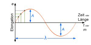
You have to see a wave in whole and slice it into 4 parts 90° apart. So you start at 0°, go to the top positive, down to zero again, then to top negative and back to zero. This is a single sound wave. Depending of frequency, this takes some time. For 50 Hz the whole cycle takes 1/50=0.02seconds. For 100Hz it is 0.01sec.
The wave travels at 340m/s which make a 50Hz wave 17m long. So at a distance of 4.25m from a wall, there is cancelation.
This is a very corse way of describing in room acoustics, more or less useless to be honest, as any object around the speaker, wall, ceiling and floor affect the sound energy at the listening point.
KEF was very good at inducing physics into advertising and leaving the sense in the dark, knowing most customers would not even try to understand. Like talking about magic "acoustic Butterworth x-over" without explaining what simple idea was behind it, used by any measuring speaker constructor anyway.
I think they still do it...
Attachments
Last edited:
- Home
- Loudspeakers
- Multi-Way
- Port underneath cabinet, good or bad design?