This is my new 6 Watt amplifier.
Now that I have ended LU1014D Small Amplifier.
This amp uses EXICON ECX10N20 Lateral MOSFET TO-247 in output.
I be back later with details and schematics.
I hope some guy is willing to draw PCB files, when the time comes.
This amplifier has THD 0.0009% 1W 8ohm in SPICE Simulation.
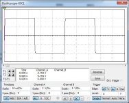
First image shows squarewave at 20kHz 4Vpeak 8ohm.
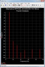
Second image shows Fourier Analysis spectrum. Mostly 2nd harmonic.
Now that I have ended LU1014D Small Amplifier.
This amp uses EXICON ECX10N20 Lateral MOSFET TO-247 in output.
I be back later with details and schematics.
I hope some guy is willing to draw PCB files, when the time comes.
This amplifier has THD 0.0009% 1W 8ohm in SPICE Simulation.
First image shows squarewave at 20kHz 4Vpeak 8ohm.
Second image shows Fourier Analysis spectrum. Mostly 2nd harmonic.
Attachments

IMO, you are now on the route to guaranteed success. 👍
I have amplifier with lateral MOSFETs on the bench for some time and it offers a lot.
Basic output stage with ECX laterals provides short and steeply falling distortion spectrum. Adding NFB pushes distortion very low.
FWIW, it is easy to get over MHz bandwidth and close to 100 V/us slew rate, even with such low supply voltage, while amplifier is stable with any capacitive load. I’m talking real measured data, not simulation.
My amplifier is with output stage enclosed in opamp NFB loop. Distortion is impossible to measure without professional equipment.
More important is sound. Not much point in pushing subjective superlatives, but it will be my reference amplifier. Most important for me is fact that it can be listened for the whole day with not a hint of listening fatigue.
Thanks, @tombo56
EXICON Laterals seems to be very robust.
Even the TO-247 can take a lot of heat.
https://www.profusionplc.com/type/lateral-mosfet
I am simulating with two ECX10N20.
It is Class A single end.
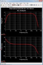
I have added a 100pF cap in the loop. This will limit the bandwidth to 1MHz -3dB.
See image:
EXICON Laterals seems to be very robust.
Even the TO-247 can take a lot of heat.
https://www.profusionplc.com/type/lateral-mosfet
I am simulating with two ECX10N20.
It is Class A single end.
I have added a 100pF cap in the loop. This will limit the bandwidth to 1MHz -3dB.
See image:
Attachments
Last edited:
Yes, it is same kind of transistor.
They are both Lateral MOSFET. ECX10N20 and 2SK1058.
Is 2SK1058 also TO-247?
No, 2SK1058 is TO-3P.
ECX10N20 can take 125 Watt. 2SK1058 can take 100 Watt.
But is no big difference.
They are both Lateral MOSFET. ECX10N20 and 2SK1058.
Is 2SK1058 also TO-247?
No, 2SK1058 is TO-3P.
ECX10N20 can take 125 Watt. 2SK1058 can take 100 Watt.
But is no big difference.

Nice of you.If the schematic is not too complicated, I can offer to design a pcb.
The schematic is mostly like my 'LU1014D Small Amplifier'.
Only now there are two TO-247 ECX10N20 transistors.
There is only one 2W resistor. Rest is 0.6W standard resistors.
Not any SMD, Please. Only through hole components.
I have Sprint Layout program. It can also import and export Gerber.
I will wait to put schematic of this design.
Because I might do some changes. And too many versions make some trouble.
I am still working on it.
It works already, but there can be improvments to make.
Let us take it slow.
It is Single End Class A, so a big heatsink is to recommend.
Two channels on one heatsink makes almost 40 Watt dissipation.
And one transformer should be 200-300VA 2x15VAC. It will serve both channels.
Last edited:
I may take a look at ALF08. This is new for me.You can add to the list of equivalents, Samelab ALF08 series, used in F7.
I also have a bunch of those equivalent TO-3 lateral Mosfet (2sk134/2sj49)This is ALSO relevant to my interests. I had high hopes for the recent LU/LD designs since I have some already mounted to the aluminum IMS adapters, but I also have some TO3 laterals begging for a newish design…
I really enjoy theses theoretical designs, regardless.
but ALL the power amplifiers I’ve listened to that uses lateral Mosfet weren’t to my liking (i usually close the amplifier after 30 minutes) so I’m hoping this one will be different. It would be nice if the PCB designer could accommodate the use of TO-3 😀
Thanks in advance Lineup
Eric
Last edited:
The difference in this amplifier is differential JFET input.
And also that it works in Single Ended pure Class A.
This means a very low effiency.
Amplifier draws almost 40 Watt to output only 6.8 Watt.
For having higher efffiency you must use Push-Pull and eventually Class AB.
Probably those amplifier you have listened to use that way.
About TO-3.
I will tell PCB files makers to not have transistor onto the PCB.
Instead it will be 3 pads and connected by wires.
Transistor on heatsink and 3 wires to the PCB.
This will make you to use any power transistors.
- Home
- Amplifiers
- Pass Labs
- Alternative 6 Watt Amplifier with EXICON Lateral MOSFET