This is a question of general interest to those designing or modifying amplifiers, not just this one kit.
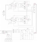
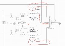
Is anyone but me concerned about running the 6P14 (or EL84) output tubes at ~350 volts in this amplifier? Isn't this voltage going to eat up the tubes very quickly? I don't want that. Schematic with suggested voltages from the building directions is attached.
The kit comes with what is labeled a "spare" zener diode that is 91 volts per the label instead of 100 volts like the others. That's in there to reduce the regulated screen voltage by 9 volts I assume? I am getting 316V on the regulated screen output when spec is 290V-305V.
Edit: I am well aware of the option of using a bucking transformer, and I am not interested in that solution for several reasons. As with most Chinese amplifiers, it is designed for 110VAC not the 121VAC that I have at my wall outlet.
Update: installing the 91V zener diode to replace one of the 100V zener diodes produced a perfect 297V on the regulated screen voltage.
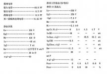
6P14 tube - translated from actual Chinese specs (EL84 is similar):
Performance Parameters
Filament voltage (Uf)=6.3V
Filament current (If)=0.76A
Anode voltage (Ua) =256V
Anode current (Ia) = 48±8mA
Second gate voltage (Ug2) = 256V
Second gate current (Ig2) ≤7mA
Transconductance (S) ≥9mA/V
Limit Application Data
Maximum filament voltage (UFMax) =7V
Minimum filament voltage (Ufmin) =5.7V
Maximum anode voltage (Uamax) =300V
Maximum second gate voltage (Ug2max) = 300V
Maximum filament and cathode voltage (Ufkmax) ±100V
Maximum anode dissipation power (Pamax) = 12W
Maximum second pole dissipated power (Pg2max) = 2W
Maximum cathode current (Ikmax) = 65mA
Maximum first gate resistance (Rg1max) = 1Mohm
Is anyone but me concerned about running the 6P14 (or EL84) output tubes at ~350 volts in this amplifier? Isn't this voltage going to eat up the tubes very quickly? I don't want that. Schematic with suggested voltages from the building directions is attached.
The kit comes with what is labeled a "spare" zener diode that is 91 volts per the label instead of 100 volts like the others. That's in there to reduce the regulated screen voltage by 9 volts I assume? I am getting 316V on the regulated screen output when spec is 290V-305V.
Edit: I am well aware of the option of using a bucking transformer, and I am not interested in that solution for several reasons. As with most Chinese amplifiers, it is designed for 110VAC not the 121VAC that I have at my wall outlet.
Update: installing the 91V zener diode to replace one of the 100V zener diodes produced a perfect 297V on the regulated screen voltage.
6P14 tube - translated from actual Chinese specs (EL84 is similar):
Performance Parameters
Filament voltage (Uf)=6.3V
Filament current (If)=0.76A
Anode voltage (Ua) =256V
Anode current (Ia) = 48±8mA
Second gate voltage (Ug2) = 256V
Second gate current (Ig2) ≤7mA
Transconductance (S) ≥9mA/V
Limit Application Data
Maximum filament voltage (UFMax) =7V
Minimum filament voltage (Ufmin) =5.7V
Maximum anode voltage (Uamax) =300V
Maximum second gate voltage (Ug2max) = 300V
Maximum filament and cathode voltage (Ufkmax) ±100V
Maximum anode dissipation power (Pamax) = 12W
Maximum second pole dissipated power (Pg2max) = 2W
Maximum cathode current (Ikmax) = 65mA
Maximum first gate resistance (Rg1max) = 1Mohm
Attachments

Last edited:
All the classic amps (except car radios) ran EL84 past 300V. Thousands of guitar amps run old and new EL84 past 350V; even 400V (which used to be the more expensive 7189 rating). EL84 is about the cheapest power tube ever made.
Do you want to look good or live forever?
Don't worry about it.
(I know nothing about Russian similars. If the guitar gang run them, they will hold up.)
Do you want to look good or live forever?
Don't worry about it.
(I know nothing about Russian similars. If the guitar gang run them, they will hold up.)

High current is what kills them. Looks like those are biased at just over 85% which is pretty hot for a PP amp. I will say those EL84 tubes like being run pretty hot to sound good. Also remember it's the voltage across the tube, not from plate to ground that matters.
Is anyone but me concerned about running the 6P14 (or EL84) output tubes at 300 volts in this amplifier kit, which appears to be the maximum voltage for both tubes? Isn't this voltage going to just eat up the tubes very quickly? I don't want that.
Don't worry about 300V plate, so long as power dissipation is not over the limit.
According to schematic the tube current is approx 35mA at 300V which gives 10.5W, should be safe.
The zener string together with the transistor stuff form a voltage regulator for the screen grids.The kit comes with what is labeled a "spare" zener diode that is 91 volts per the label instead of 100 volts like the other three. That's in there to reduce this voltage by 9 volts, I assume because the transformer is labeled to have 115V input and not USA 120V, correct? Schematic attached.
Therefore screen voltage will not depend on mains voltage, significantly.
(Plate voltage will, though) ...
However, zeners have tolerances, and exact voltage also depends on temperature and current, especially the high voltage types.
I think what they suggest is, that when the screen voltage comes out much higher than 300V, you can replace one or two of the 100V zeners with 91V type, to keep screen voltage below 300, which is desirable (more than plate v).
Did you notice that the schematic is incomplete;
The global feedback will only work if the unlabelled wire on the output transformer secondary is grounded.
Otherwise your amp will play very loud, may hum and sound a little distorted ...
The global feedback will only work if the unlabelled wire on the output transformer secondary is grounded.
Otherwise your amp will play very loud, may hum and sound a little distorted ...
It is hard to tell if the 6P14 will last very long.
Russian 6P14P plate 250V, screen 250V.
I remember the SV83 tube.
It was similar to the EL84, but the screen was only rated at 250V and 1.5 Watt dissipation.
It really did struggle, or die in most EL84 circuits.
If you used it properly, it was a very good tube.
EL84 screen max is 300V and 2.0 Watts dissipation.
Caution: Often different "equivalent" tubes have different pin-out connections.
It is not always just the maximum ratings, it is the connections.
What isn't mentioned here is.... with 300 volts on the plate-to-ground, you also have 8 to 10 or even 12 volts-to ground on the cathode.
That means the tube really only sees around 290v on it.
And as mentioned, if it's a decent branded tube, it's nothing to even discuss or worry over.
I've got amps running EL84's and 7189A's running at 300 to 320v and they've lasted for years now.
That means the tube really only sees around 290v on it.
And as mentioned, if it's a decent branded tube, it's nothing to even discuss or worry over.
I've got amps running EL84's and 7189A's running at 300 to 320v and they've lasted for years now.
High current is what kills them. Looks like those are biased at just over 85% which is pretty hot for a PP amp.
How do you calculate that, and would you leave it as-is?
Love your YouTube channel! Thanks!
We estimated from the numbers given in the schemattic:
10V at the cathodes of the output tubes which have a common cathode resistor of 150 ohm.
Apply Ohm's law, I=V/R=10V/150Ohm=0.067A or 67mA.
This current is shared between both tubes. If both had identical parameters, thats 33mA per tube ...
that is cathode current, which comprises plate current plus screen current.
Russian 6P14P:It is hard to tell if the 6P14 will last very long.
Russian 6P14P plate 250V, screen 250V.
I remember the SV83 tube.
It was similar to the EL84, but the screen was only rated at 250V and 1.5 Watt dissipation.
It really did struggle, or die in most EL84 circuits.
If you used it properly, it was a very good tube.
EL84 screen max is 300V and 2.0 Watts dissipation.
Caution: Often different "equivalent" tubes have different pin-out connections.
It is not always just the maximum ratings, it is the connections.
Max Va (Pa<=8W) 400V
Max Va (Pa>8W) 300V
Max Vg2 300V.
Apply Ohm's law
It can't be that simple! 🙂
I haven't done anything with circuits and tube amplifiers for about 30 years. I knew enough to get by and to not blow anything up or electrocute myself back then, but sadly, after not touching the hobby for so long, a lot of what I used to know has evaporated from my memory. Just for fun, and to re-learn and to get back into the hobby, I bought this little $350 tube amp kit that xraytonyb built and tested in a video series:
Part 1:
The kit has been updated since xraytonyb built it. They have removed the awful loudness circuitry that was included, which was the first mod that xraytonyb made when he built it.
I haven't started to solder anything yet. I'm thoroughly reviewing everything to make sure I get as much understanding and learning under my belt as possible before I pick up the soldering iron. More questions and answers, including a link to the latest directions (67 pages) can be found here for anyone interested in this amplifier:
https://www.diyaudio.com/community/...s-before-i-build-maybe-during-if-i-do.394962/
I have translated the directions from Chinese to English, and also managed to translate the tube specifications from Chinese to English. They were very difficult to get.
It is hard to tell if the 6P14 will last very long.
I have my doubts, but they are good enough to get me started with the kit. The manufacturer recommends using EL84 and ECC85 tubes. They actually put them on the schematic, but that's not what comes in the box. It comes with 6P14 and 6N1 Chinese tubes. If this little amp actually works (meaning I don't blow something up) and it sounds decent, then maybe I'll invest in the better tubes.
Did you notice that the schematic is incomplete;
The global feedback will only work if the unlabelled wire on the output transformer secondary is grounded.
Thanks so much for catching that. I was hoping someone would look at the schematic and catch any errors. I pieced that schematic together from the Chinese instructions for the kit, and I filled in things that were missing. They left that off, and I didn't even notice. I checked the instructions to make sure they caught it there, and yes they do instruct to run that to the common ground point. I removed significant portions of the circuit that were devoted to the "magic eye" tubes, which I am not going to use. I'm also not putting the included orange LEDs underneath the tubes. I just want sound, not a "visual experience" although some might like those features.
This little amplifier kit is a learning experience and a memory refresher after a 30 year absence from the hooby.
Attachments
What isn't mentioned here is.... with 300 volts on the plate-to-ground, you also have 8 to 10 or even 12 volts-to ground on the cathode.
That means the tube really only sees around 290v on it.
Thank you! This is a learning experience, and that little tip is a nice nugget of knowledge for me to remember. 🙂
I didn't expect this single ( and I thought simple) question to result in so much learning.
I want to thank everyone here. This forum is excellent and everyone here is so helpful.
This current is shared between both tubes. If both had identical parameters
Now, I was wondering about that. This may be a silly novice question, but is there a simple way to test this as I am certain that the tubes are not matched in any way.
If you like it’s sound pick up some Russian 6p14p-EV tubes. They are the mil spec tubes and are slightly higher rated and longer lasting. The sound great too! You can get them out of Ukraine still much delay. The war hasn’t stopped me getting lots of tubes from there.
If you like it’s sound pick up some Russian 6p14p-EV tubes. They are the mil spec tubes and are slightly higher rated and longer lasting.
Yes, and here are the results of my research about different types of 6P14P:
6P14P (Russian)
All these Russian tubes have the identical electrical characteristics but different lifespans:
6P14P = 3000hr
6P14P-V = 1000hr
6P14P-EV = 5000hr*
6P14P-ER = >10000hr
6P14P-K = 3000hr and vibration resistant
*6P14P-EB is the same tube as 6P14P-EV
- maximum rating for filament voltage is 5.7 - 7 for 6P14P, 6P14P-V (6n14p-B) and 6P14P-EV (6n14n-EB)
- maximum rating for filament voltage is 6.0 - 6.6 for 6P14P-ER (6n14n-EP), typical for long life tubes
- 6P14P-ER (6n14n-EP) also has higher filament current - 800 ±60mA vs. 760±60mA for the others
If anyone ever wants the exact specs on the Chinese 6P14, which are not easy to find, and which must be translated from Chinese, here are the best three translations I have been able to do, all taken from actual tube manufacturers in China. If anyone has corrections, please note them. Translations are not perfect.
【 用途 】 旁 热 式 阴极 五 极 管 /低频 功率 放大
【 性能 参数 】
灯丝 电压 (Uf)=6.3V;
灯丝 电流 (If)=0.76A;
阳极 电压 (Ua) =256V ;
阳极 电流 (Ia)= 48±8mA ;
第二 栅极 电压 (Ug2) = 256V;
第二 栅极 电流 (Ig2) ≤7mA ;
跨 导 (S) ≥9mA /V;
输出 功率 (Po) ≥3W ;
| 非线性 失真 系数 (Kf)≤10 %
注 :
1Ug1 ~ = 3.4V,ZL=5.2k 时 .
( 极限运用 数据 )
最大 灯丝 电压 (UFMax ) =7V;
最小 灯丝 电压 (Ufmin) =5.7V;
最大 阳极 电压 (Uamax ) =300V ;
最大 第二 栅极 电压 (Ug2max ) = 300V;
最大 灯丝 与 阴极 间电压 (Ufkmax ) ±100V ;
最大 阳极 耗散 功率 (Pamax ) = 12W ;
最大 第二 柵极 耗散 功率 (Pg2max ) = 2W ;
| 最大 阴极 电流 (Ikmax )= 65mA ;
最大 第一 栅极 电阻 (Rg1max ) = 1M2
【 Application】
Indirect heated cathode pentode
low-frequency power amplification
【 Performance Parameters 】
Filament voltage (Uf)=6.3V
Filament current (If)=0.76A
Anode voltage (Ua) =256V
Anode current (Ia) = 48±8mA
Second gate voltage (Ug2) = 256V
Second gate current (Ig2) ≤7mA
Transconductance (S) ≥9mA/V
Nonlinear distortion factor (Kf) ≤ 10 %
Concentrate:
1Ug1 ~ = 3.4V, ZL=5.2kohm
(Limit Application Data)
Maximum filament voltage (UFMax) =7V
Minimum filament voltage (Ufmin) =5.7V
Maximum anode voltage (Uamax) =300V
Maximum second gate voltage (Ug2max) = 300V
Maximum filament and cathode voltage (Ufkmax) ±100V
Maximum anode dissipation power (Pamax) = 12W
Maximum second pole dissipated power (Pg2max) = 2W
Maximum cathode current (Ikmax) = 65mA
Maximum first gate resistance (Rg1max) = 1Mohm
【Application】
Parathermal cathode pentode/low-frequency power amplification
【Performance parameters】
Filament voltage (Uf) = 6.3V
Filament current(If)=0.76A
Anode voltage (Ua) = 256V
Anode current (Ia) = 48±8mA
Second gate voltage (Ug2) = 256V
Second gate current (Ig2) ≤7 mA
Transconductance (S) ≥ 9mA/V
Output power (Po) ≥ 3W
Nonlinear distortion factor (Kf) ≤10%
Concentrate:
(1)Ug1~=3.4V, ZL=5.2kohm
(Extreme usage data)
Maximum filament voltage (UFMax) = 7V
Minimum filament voltage (Ufmin) = 5.7V
Maximum anode voltage (Uamax) = 300V
Maximum second gate voltage (Ug2max) = 300V
Maximum filament and cathode voltage (Ufkmax) ± 100V
Maximum anode dissipation power (Pamax) = 12W
Maximum second pole dissipation power (Pg2max) = 2W
maximum cathode current (Ikmax) = 65mA
Maximum first gate resistance (Rg1max) = 1Mohm
Attachments
I personally don't touch chinese-made tubes.
The Russian/Slovac are new manufacture, and reasonably ok.
However since I have an ample stock of "new-old-stock" American made tubes, that is what I prefer.
Sylvania, RCA, GE, Raytheon, etc.
The Russian/Slovac are new manufacture, and reasonably ok.
However since I have an ample stock of "new-old-stock" American made tubes, that is what I prefer.
Sylvania, RCA, GE, Raytheon, etc.
I personally don't touch chinese-made tubes.
Came in the kit = "free." Good enought to make sure this amplifier actually works after I assemble it. Then I can change the tubes later if it works and I don't blow something up.
- Home
- Amplifiers
- Tubes / Valves
- Run power tubes at max voltage?