Hi,
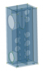
I’m building a 12” fullrange speaker, and I’m a bit confused what is the preferred wayin speaker cabinet design. I’m a mechanical engineer and I have an opportunity to run complex FEA simulations. I had a base design, what looks too flexible, so I started to reinforce it.
I’ve run Steady State Dynamic (Modal) analysis, do check the dynamic behavior of the cabinet. The result is very confusing:
Base design:
Modified design:
My guess is that the new design will have less influence to the sound because if the side of the cabinet act like the speaker membrane, and generating sound waves, the amplitude will be much smaller, and the membrane are is also much smaller.
Is this assumption correct?
Adding more reinforcement moving the resonant freq. up, and reducing the “membrane are”.
Another interesting thing is that the displacement of the 2nd and 3rd resonant frequencies much less, so have to focus on the first.
I’m building a 12” fullrange speaker, and I’m a bit confused what is the preferred wayin speaker cabinet design. I’m a mechanical engineer and I have an opportunity to run complex FEA simulations. I had a base design, what looks too flexible, so I started to reinforce it.
I’ve run Steady State Dynamic (Modal) analysis, do check the dynamic behavior of the cabinet. The result is very confusing:
Base design:
- First resonant freq is around 80Hz
- max. normal displacement is 0.1mm
- max. normal acceleration is 8G
Modified design:
- First resonant freq. is around 180Hz
- max normal displacement is 0.03mm
- max normal acceleration is 50G
My guess is that the new design will have less influence to the sound because if the side of the cabinet act like the speaker membrane, and generating sound waves, the amplitude will be much smaller, and the membrane are is also much smaller.
Is this assumption correct?
Adding more reinforcement moving the resonant freq. up, and reducing the “membrane are”.
Another interesting thing is that the displacement of the 2nd and 3rd resonant frequencies much less, so have to focus on the first.
It's best to force resonances to higher frequencies as high frequencies have less acoustical power.
Bracing helps with this too.
Bracing helps with this too.

What is the bandpass of the woofer. Any box resonance is ideally higher than the XO. 180 is not that low. The high G likely implies higher Q, that is good, takes a lot more energy to rxcite the resonance.
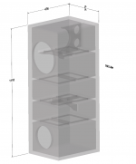
Can you post a picture of your box?
dave
Can you post a picture of your box?
dave
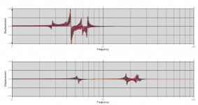
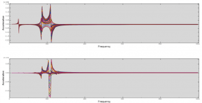
I have attached two result plots, for better understanding.
I've extracted the side wall normal direction nodal displacement, and acceleration. Each line in the graph represent of the movement or acceleration of a node.
Top plot is always the base design and bottom plot is the modified
I've extracted the side wall normal direction nodal displacement, and acceleration. Each line in the graph represent of the movement or acceleration of a node.
Top plot is always the base design and bottom plot is the modified
Attachments

In my designs, I use thick lumber/walls to eliminate any chance of cabinet resonances or at least make them inaudible, usually at least 3/4 inch thickness.
Thoughtful bracing is sometimes needed.
I want to hear what the speakers(s) reproduce, not the cabinet.
And then I design the speakers "voicing" by the crossover network.
Thoughtful bracing is sometimes needed.
I want to hear what the speakers(s) reproduce, not the cabinet.
And then I design the speakers "voicing" by the crossover network.
What is the bandpass of the woofer. Any box resonance is ideally higher than the XO. 180 is not that low. The high G likely implies higher Q, that is good, takes a lot more energy to rxcite the resonance.
Can you post a picture of your box?
dave
There is a fullrange driver, here is the specs
https://www.commonsenseaudio.com/an12classicspecs.jpg
One thing what also have to keep in mind, mass of the brace (and generally any mass f.ex bitumen sheets) have a big influence to the sidewall displacement.
So have to design the brace as light as possible
The box. I am somewhat familair with the driver.
Given a FR you want to push resonances up ideally pushing for 500 Hz or so.
Pictures of the box?
dave
Given a FR you want to push resonances up ideally pushing for 500 Hz or so.
Pictures of the box?
dave
bitumen sheets
Note that those tend to be counterproductive, pushing resonances down as they add no stiffness and increase mass. Also lowers the Q of any potntial resonance making it easier to hear.
dave
Brace the side walls and dispense with the bitumen sheets as Dave suggests.One thing what also have to keep in mind, mass of the brace (and generally any mass f.ex bitumen sheets) have a big influence to the sidewall displacement.
So have to design the brace as light as possible
What material are you using for the box?
jeff
Last edited:
Totally agree. That is my conclusion too. Bitumen sheets has better viscoelastic damping constant, but damping only helps in time domain, not in frequency domain.Note that those tend to be counterproductive, pushing resonances down as they add no stiffness and increase mass. Also lowers the Q of any potntial resonance making it easier to hear.
dave
It is huge. So pushing the resonant freq. to 500Hz is not realisticThe box. I am somewhat familair with the driver.
Given a FR you want to push resonances up ideally pushing for 500 Hz or so.
Pictures of the box?
dave
Attachments
It's the same thing in this respect. Also, lowering the Q is necessary toward eliminating it.but damping only helps in time domain, not in frequency domain.
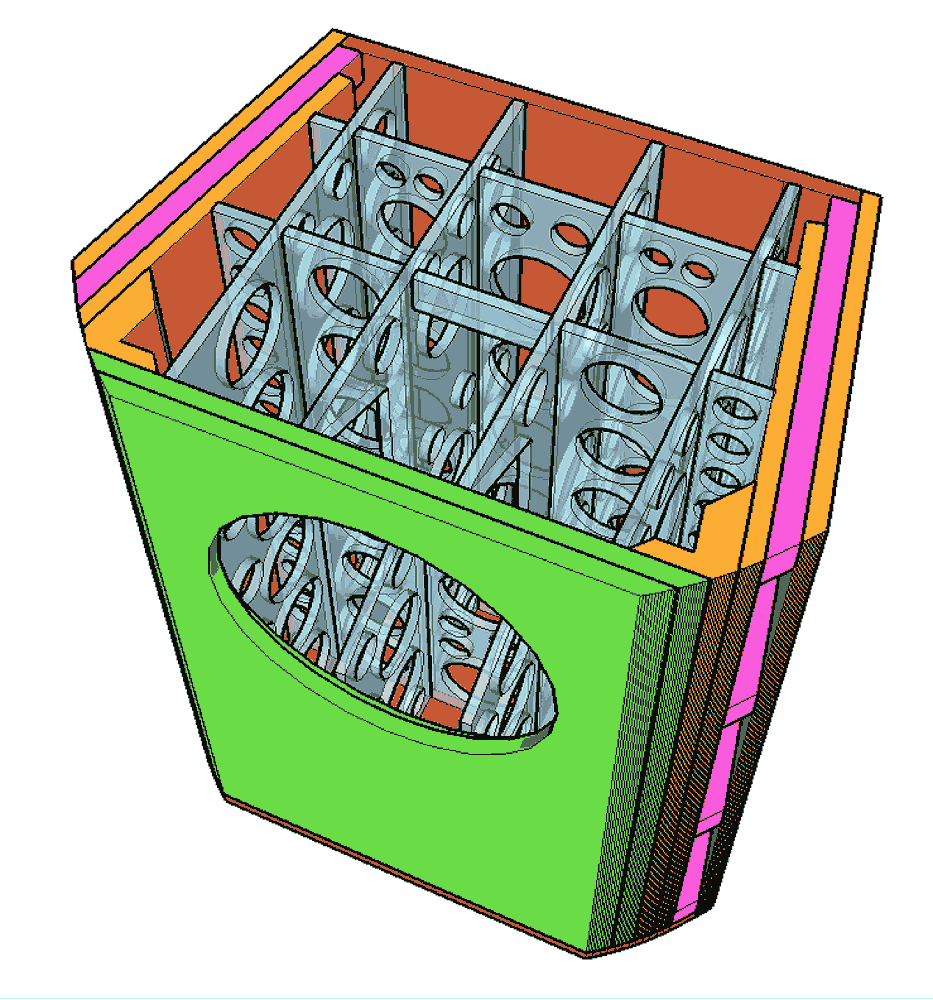
To start off the braces in tht box are incorrectly oriented.
Guidline 1: The subpanelcreated by a brace should have a larger aspect ratio than the panel being braced.
Your bracing will be much more effective if running vertically.
135 litres
dave
Guidline 1: The subpanelcreated by a brace should have a larger aspect ratio than the panel being braced.
Your bracing will be much more effective if running vertically.
135 litres
dave
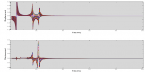
I did some calculation again. I've modified the bracing and changed the orientation to vertical.
I want to keep the volume behind the driver as clear as possible to avoid that reflections goes back to the driver
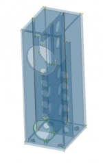
The result shows, that the sidewall deformation is almost the double, the resonant frequency is increased from 180Hz to 210Hz (bottom picture) but the top of the picture shows that the other direction (normal to front wall) almost 18times worst. Huge deflection around 160Hz.
Of course it is possible to optimize it, and add more vertical brace, change the opening shape and size, but my feeling is that there is no general rule, vertical or horizontal is better, all depends on the rigidity (geometry) , damping (we can't change too much, material dependent) and the mass.
I want to keep the volume behind the driver as clear as possible to avoid that reflections goes back to the driver
The result shows, that the sidewall deformation is almost the double, the resonant frequency is increased from 180Hz to 210Hz (bottom picture) but the top of the picture shows that the other direction (normal to front wall) almost 18times worst. Huge deflection around 160Hz.
Of course it is possible to optimize it, and add more vertical brace, change the opening shape and size, but my feeling is that there is no general rule, vertical or horizontal is better, all depends on the rigidity (geometry) , damping (we can't change too much, material dependent) and the mass.
Attachments
I want to keep the volume behind the driver as clear as possible to avoid that reflections goes back to the driver
Something i do as well, i do brace the driver against the back, top, bottom so as to remove energy from the baffle, and distribute it more evenly thruout the box (the hope is that it never gets high enuff in any part of the box to actual excite potential ringong.
Are your braces centred? They should not be.
dave
Braces are slightly off from center.
Meantime I’m thinking about maybe the Strain Energy Density could be a useful parameter as well to check how much energy is stored when it deforming.
Meantime I’m thinking about maybe the Strain Energy Density could be a useful parameter as well to check how much energy is stored when it deforming.
Storing it should be fine as long as it is dissipated as heat, more interesting would be how much and when the energy is released (if it is).
Also as Geddes points out, if different subpanels are going in different directions net radistion can be very much smaller,
dave
Also as Geddes points out, if different subpanels are going in different directions net radistion can be very much smaller,
dave
Because of the behavior of wood almost all the stored energy ringing back, only a few percentage of the stored energy dissipates as a heat according to the definition of damping coefficients what is roughly 0.02 in wooden materials.Storing it should be fine as long as it is dissipated as heat, more interesting would be how much and when the energy is released (if it is)
- Home
- Loudspeakers
- Full Range
- Physics of speaker cabinet