Hi guys!
Recently I started working on tube phono preamp. I'm simulating my design with LTSpice and I realised that I'm not quiet sure what is the typical thd for sucha device.
I expect that in comparsion with solid states the tube will have higher THD? I havenť found any all tube phono preamps online to check so I would really use your help.
Thank you.
Here are some practical measurements:
https://www.diyaudio.com/community/threads/measured-phono-signal-levels.372498/#post-6675771
https://www.diyaudio.com/community/threads/measured-phono-signal-levels.372498/#post-6675771
It depends if the riaa is a feedback type or without.Hi guys!
Recently I started working on tube phono preamp. I'm simulating my design with LTSpice and I realised that I'm not quiet sure what is the typical thd for sucha device.
I expect that in comparsion with solid states the tube will have higher THD? I havenť found any all tube phono preamps online to check so I would really use your help.
Thank you.
Feedback types can be low as 0.06 % ( Dynaco PAS) in a well designed circuit. As tubes typically has less
amplifying elements then transistor dito the total amplification is often minimum to cope with the
riaa curve.
Non-feedback tube riaa's has more dist, but seldom the amount that disturbes musical experience.
For what it's worth, my valve MM phono preamplifier has a distortion of about 0.05 % at 1 kHz at 1 V RMS output level.
Normally the oveload of a MM phono is high.
So the THD at the standard level, p.e. 3 mV, is low.
This is a THD vs frequency of one my phono, Junior phono, with an input od 4,1 and 8,2 mV .
The gain is around 42 dB
In this cas the max input for 1% (around 8,9 volt out) is 30 mV at 1kHz.
It has a passive Riaa.
Good enough

So the THD at the standard level, p.e. 3 mV, is low.
This is a THD vs frequency of one my phono, Junior phono, with an input od 4,1 and 8,2 mV .
The gain is around 42 dB
In this cas the max input for 1% (around 8,9 volt out) is 30 mV at 1kHz.
It has a passive Riaa.
Good enough
Phono THD is non-issue because signal level is very low.

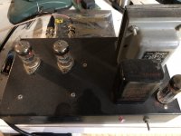
I built an RJM phono preamp some years ago. Wonder what it would measure on the distortion analyzer?
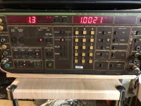
Ok a half hour warm up with the analyzer and phono stage and the results are in. Here is the schematic. https://phonoclone.com/diy-pho3.html
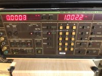
I fed in 10mV at 1Khz and measured exactly 600mV out with my calibrated bench meter. The analyzer reads slightly lower at 582mV. THD is reading 1.3%. For reference when the analyzer is in loopback mode at 1V it hovers around 0.0007% to 0.0009%.
I fed in 10mV at 1Khz and measured exactly 600mV out with my calibrated bench meter. The analyzer reads slightly lower at 582mV. THD is reading 1.3%. For reference when the analyzer is in loopback mode at 1V it hovers around 0.0007% to 0.0009%.
Attachments

Please look at a few phono cartridge reviews.
You will have to look at several reviews, before you find one that lists measurements of the 2nd harmonic distortion, and the 3rd harmonic distortion.
Unless you have a recording that has very high signal levels, and a phono preamp with enough gain to cause it to be near clipping . . .
The phono cartridge; the Vinyl record; and the cutting head & amplifier; are the major contributors of the 2nd and 3rd harmonic distortion, as well as the intermodulation distortion too.
As bad as some might consider all this to be, it sounds Wonderful! . . . Right?

Classic distortion analyzers remove the fundamental and measure the sum of everything left. Works fine at high levels, but at low levels noise can dominate. Decent valve phono stages are certain to be dominated by noise, because actual distortion at signal level is so low.
One thing that we take for granted is the inherent monotonicity of class A amplifiers, universally used for valve preamps. This is not guaranteed to be true for monolythic op-amps, however attractive they may otherwise be - sufficiently heavy loading brings usual monolythic op-amps into danger of crossover distortion. Valves run hot enough to avoid that issue.
All good fortune,
Chris
Some classic distortion analyzers not only remove the fundamental, they also can remove very low frequencies and some of the very high frequencies.
In that case, pretty much only the 2nd and 3rd harmonics are all that is left in the measurement (and the 2nd and 3rd are the major harmonic energy).
Hum is eliminated, and for a 1kHz test tone, most of the noise is in the frequencies covering the fundamental, 2nd and 3rd harmonics, with little noise at higher frequencies than that.
Of course those test houses that are fortunate enough to have a Tektronix classical 7L5 spectrum analyzer do not have any of the above listed measurement problems. You can set the resolution bandwidth filter narrow, and that reduces the noise floor, but does not reduce the signal level of the fundamental, and does not reduce the level of the 2nd and 3rd harmonic distortions.
All is well in that measurement, since the analyzer noise floor is very near to ktB,
Good and accurate measurements of phono cartridges are entirely possible; of course the harmonic distortion of the cutter head, and the cutting amplifier will be part of the measurement's distortion numbers. You can not separate those distortions out.
Well, you could measure the distortion of the cutting amplifier, but there is no certainty whether the amplifier's 2nd harmonic distortion adds to, or subtracts from the cartridges 2nd harmonic (partial cancellation, or partial addition).
But, those same harmonic distortions do not go away, just because the signal you listen to is music, instead of a single test tone.
Think of the cutter amplifier, cutting head, and. phono cartridge as a complete sub-system that generates harmonic distortion.
Last edited:
There is a fundamental difference between feedback and passive (inter-stage) RIAA equalization. With passive, you attenuate the 2nd, 3rd etc. distortion components and noise of the preceding stage, just like as you attenuate the higher frequencies of the audio signal. End result is lower noise, lower distortion and better overload margin compared to a feedback design using the same active components.
I would disagree with really all of that. Noise is dominated by the input stage, sometimes in combination with the source impedance and loading resistor. And the best possible overload margin and distortion come from a long loop feedback. Noise is also reduced by feedback, including (hopefully insignificant) contributions from stages that would be following the EQ in lossy designs.
Valve phono stages have such generous overload margins and low distortion as to not matter, but in principle a loop feedback is better in both regards. Also better for low input capacitance.
All good fortune,
Chris
Valve phono stages have such generous overload margins and low distortion as to not matter, but in principle a loop feedback is better in both regards. Also better for low input capacitance.
All good fortune,
Chris
Ok this is a personal preference. Either concept could perform very good. I think we can agree that THD <0.1% at full output is a realistic goal. Large overload margin is more important in my opinion.
And the opposite is true. Feedback reduces dist and extends frequency band/accuracyThere is a fundamental difference between feedback and passive (inter-stage) RIAA equalization. With passive, you attenuate the 2nd, 3rd etc. distortion components and noise of the preceding stage, just like as you attenuate the higher frequencies of the audio signal. End result is lower noise, lower distortion and better overload margin compared to a feedback design using the same active components.
It really is horses for courses. In general, feedback RIAA equalisation works better with solid state because it's easy to get enough gain to still have lots of (distortion reducing) feedback even at 50Hz where we need lots of gain. Passive equalisation usually works better with valves because it's quite easy to swing 20VRMS with reasonably low distortion. As has already been mentioned, 0.1% THD is a sensible goal at nominal peak output. But overload margin is even more important because of clicks and bangs that easily produce larger signals than the music. The tricky thing is to juggle the design to give low noise and good overload margin. In general, if you've done that, low distortion tends to happen naturally. And don't forget that the cartridge is frighteningly nonlinear, making pre-amplifier distortion less of an issue. The other thing to be wary of is getting the RIAA right. That is much harder than you might think (as proven by numerous commercial designs). Oh, and make sure it doesn't hum. DC heaters and remote power supply. No mains transformers or turntable motors nearby.
Indeed. But I have other priorities.Feedback reduces dist and extends frequency band/accuracy
- Home
- Amplifiers
- Tubes / Valves
- THD in tube phono preamp