Hi, my name is Frane, Croatia.
Im building TL- MTM:
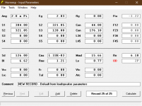
Woofers: SB16pfcr25-8
Tweeter: SB26adc
(5" augerpro waveguide)
Initial idea was to make sealed tower enclosure based on Grundig Sl1000 MTM topology from 1978. To this date best sounding speaker I've listened to - only "flaw" are 4" woofers. It is suited only for smaller rooms. (And yes - I've heard likes of Magico, PMC Fenestria etc)
However I got interested in idea of transmission line because it offers best of ported and sealed enclosure. But I never heard one, nor built one - just know some basics.
I read lot of stuff few last days on MJK site, however his MathCad sheets are not available anymore. So I started playing with Hornresp, analysing available designs. For example example TrixTrix TL and Dappolito's Thor..
What I have found is - when modeled in Hornresp - those enclosures seem to be tuned 10-15hz lower than Fs of the driver.. and that is without the stuffing which brings the tuning even 5-10hz lower.
From available information for a lowish Qts (0.35-0.4) driver tuning should be slightly higher than Fs, yet every available design I try to model seems to be tuned waaay waay lower. Even when using TL calculator on Hornresp (MJK models) with SB16pfc parameters automated tuning is always much lower than fs.
I will most likely design something like trixtrix short folded tl enclosure because it behaves well in sim, unlike Thor with its 2m long line and small offset..
My question would be.
How low should you tune TL and not run into the problems?
Any ideas and suggestions for enclosure are welcome.
Im building TL- MTM:
Woofers: SB16pfcr25-8
Tweeter: SB26adc
(5" augerpro waveguide)
Initial idea was to make sealed tower enclosure based on Grundig Sl1000 MTM topology from 1978. To this date best sounding speaker I've listened to - only "flaw" are 4" woofers. It is suited only for smaller rooms. (And yes - I've heard likes of Magico, PMC Fenestria etc)
However I got interested in idea of transmission line because it offers best of ported and sealed enclosure. But I never heard one, nor built one - just know some basics.
I read lot of stuff few last days on MJK site, however his MathCad sheets are not available anymore. So I started playing with Hornresp, analysing available designs. For example example TrixTrix TL and Dappolito's Thor..
What I have found is - when modeled in Hornresp - those enclosures seem to be tuned 10-15hz lower than Fs of the driver.. and that is without the stuffing which brings the tuning even 5-10hz lower.
From available information for a lowish Qts (0.35-0.4) driver tuning should be slightly higher than Fs, yet every available design I try to model seems to be tuned waaay waay lower. Even when using TL calculator on Hornresp (MJK models) with SB16pfc parameters automated tuning is always much lower than fs.
I will most likely design something like trixtrix short folded tl enclosure because it behaves well in sim, unlike Thor with its 2m long line and small offset..
My question would be.
How low should you tune TL and not run into the problems?
Any ideas and suggestions for enclosure are welcome.
Did you read Dappolito's article about Thor?
Thor is based on Augspurger's alignment tables for fully stuffed TL . In these tables, pipe tuning frequency is always higher than Fs.
If made correctly, your Hornresp simulations should show that.
I made TL speakers based on Augspurger's system with Seas FA22RCZ fullrange drivers and I'am very pleased with results.
Read these articles for more info:
G.L.Augspurger - Transmission Lines Updated, parts 1,2,3

@pkitt is the guy you want to talk to
Or Scottmoose.
Damping should make little to no difference in the tuning frequency.
dve

Did you read Dappolito's article about Thor?
Don’t make the same mistakes he did.
Note that the table in the MJK article are much more comprehansive.
dave
The optimum tuning frequency is based on Qts and Fs. If the driver's Qts is equal or close to 0.40, the optimum tuning frequency in a TL will be equal or close to Fs. If Qts is higher than 0.40, the optimum tuning frequency will be lower, and if Qts is lower than 0.40, the optimum tuning frequency will be higher than Fs. How much lower than or how much higher than Fs depends, of course, on how much the actual Qts differs from 0.40. Personally I prefer to use drivers with a Qts of ~0.35 to 0.50 and have seldom had good luck in TLs with drivers having a Qts below 0.30. Don't forget that the resistance of an inductor in series with the driver will increase Qts some.
Paul
Paul
Thanks Paul.
Qts is 0.4 but I'll be using 24-26awg inductors for attenuation, so I will keep added series resistance in mind.
I will trust Hornresp on this one despite it is showing that Thor is tuned to ~20hz, (seas: fs 35hz) and trixtrix to ~35hz (dayton: fs 54hz). It's more convenient than working with sheets and equations.
Frane
Last edited:
Inductors made from 24-26 AWG wire are very likely to have quite high resistance values which, in addition to increasing the effective Qts, the drivers' sensitivity will be lowered likely quite a bit. What are your goals for this build regarding f3, cabinet size and shape and complexity of the ML-TL?
Paul
Paul
Woofers have 88-90db sensitivity, depending on source. Tweeter has 90db sensitivity, but there will be some loss above 10khz due to waveguide, so likely there will be RC network, to flatten the response a bit which will lower the overall output of tweeter.
There will be baffle step loss due to 20cm front panel.. but i belive that that i will still need to bring the woofers down a bit. Complexity of TL is not the issue since it will be cut by CNC.
I had most success with ML TQWT design in Hornresp. But im leaning towards the TL. Im presuming that ML will have boomy low end simmilar to BR which I dont like. I will post few sims and sketches.
Frane
An ML-TL should not have a boomy low end if properly designed and constructed in accordance with the design. I've built for personal use both tapered and mass-loaded TLs, 2-ways and 3-ways, and I've never had an issue with boomy bass. My last build was a tapered and mass-loaded TL.
Paul
Paul
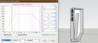
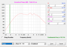
I just did modeling for a "simple" ML-TL floor-stander for a pair of these paralleled woofers in an MTM where the tweeter's center is the design center. I used internal cabinet dimensions of 8"W x 10"D x 42"H with the tweeter's center located 10" below the internal top. The mass-loading port has a diameter of 3" and a length of 4.5" with its center located 3.5" above the internal bottom. The top half of the cabinet is stuffed with polyester fiber at a density of 0.75 lb/ft3 requiring about 12 ounces total of fiber. The system tuning frequency was 34 Hz and f3 was also 34 Hz. I modeled with 0.25 ohms added in series with the woofers and the resulting 2.83v/1m sensitivity modeled at 94 dB SPL (before BSC compensation effects). Then I modeled a longer ML-TL having a line length of 60" (requiring the line to be folded) and a line area of 9"W x 7"D. The tweeter's center was located 20" from the beginning of the line and the port's center was located 10" from the end of the line. The port diameter was 3" and its length was also 3". The first half of the line was stuffed at 0.75 lb/ft3 requiring about 14 ounces total of poly fiber. The system tuning frequency was again 34 Hz and f3 was 36 Hz. The response shape of this second design had characteristics very similar to that of a negatively tapered TL (which I also modeled but just didn't get promising results). Regarding your comment about you adding 100 grams of stuffing, since I had the worksheet up for the longer ML-TL, the amount of stuffing I used was almost 400 grams (assuming I did the conversion correctly), yet when I set the stuffing density to zero, the tuning frequency increased to about 36 Hz, while f3 decreased to about 32 Hz. There's obviously some concerns about how HornResp handles stuffing effects.
Attachments
Last edited:
Thank you so much Paul! That is really effective design and one I will most likely go for.
Smooth, extended response and very easy to build.
I could 3D print port with screw cap so speaker could be turned to from ML to sealed in few seconds.
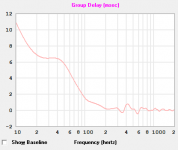
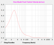
If I may ask one more thing: Mouth velocity and group delay.
How much does it effect the sound?
I compared your ML design with my overly complicated TQWT/TL? abomination 😀
ML has the edge in smoothness and extension, but delay and velocity are much lower on TL.
Smooth, extended response and very easy to build.
I could 3D print port with screw cap so speaker could be turned to from ML to sealed in few seconds.
If I may ask one more thing: Mouth velocity and group delay.
How much does it effect the sound?
I compared your ML design with my overly complicated TQWT/TL? abomination 😀
ML has the edge in smoothness and extension, but delay and velocity are much lower on TL.
Attachments
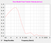
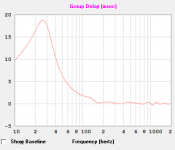
Which of my two models are you primarily interested in? And, what power input were you using that resulted in these 4 graphs? I can show you graphs for the port's air velocity, the impulse response and the system group delay from the modeling, but I don't not a separate TL velocity whatever that means.
Paul
Paul
First one, smaller version. "TL/ML velocity" is just what I've quickly written when I was saving pictures.
Its air velocity from port - or mouth in hornresp.
Its air velocity from port - or mouth in hornresp.
Oh, I now understand your attached two graphs for two different designs, one an ML and the other not. Right? Whatever, what was your input level used to generate those 4 graphs? I assume it wasn't 2.83v/1m.
That is correct: those are results for 2 different designs.
Input level was set to 2.83V by default.
But yes, SPL of 100db for pair of 88db drivers is way to high for given value.
Input level was set to 2.83V by default.
But yes, SPL of 100db for pair of 88db drivers is way to high for given value.
I was quite busy since last post, but recently I've got some time to build the speakers and do some measurements.
Here we go:
#1 Merged response (port/nearfield/anechoic)

2# Impedance

#3 Full response without gating

#4 Gated response 5ms

5# Out of phase

6# Quasi spinorama (I just rotated speaker by hand until I was cca 60° of axis)

7# Unfinished speaker standing next to reference for this build - Grundig SL1000 (1978)

This is second variant of crossover.. in the first one was drivers were measured with loudness turned on and that resulted in no baffle step loss and much more lively tweeter response. End result was.. well.. bumpy and uneven. In spite of that results were promising. Very deep and well controlled bass, deep soundstage with crazy imaging.
These posted measurements are from second crossover when speakers were measured correctly 😀
I'm yet to build crossover for other speaker and do some listening. Measurements look out of this world. Speaker covers 30-20khz within 1db.
Only problem I can see so far is that bump on 3khz of axis which may cause problem in room..
Otherwise directivity is well controlled. I might sacrifice 3db in that zone on axis for more even of axis since there is LRC filter.
But I will see after some listening test.
Here we go:
#1 Merged response (port/nearfield/anechoic)
2# Impedance
#3 Full response without gating
#4 Gated response 5ms
5# Out of phase
6# Quasi spinorama (I just rotated speaker by hand until I was cca 60° of axis)
7# Unfinished speaker standing next to reference for this build - Grundig SL1000 (1978)
This is second variant of crossover.. in the first one was drivers were measured with loudness turned on and that resulted in no baffle step loss and much more lively tweeter response. End result was.. well.. bumpy and uneven. In spite of that results were promising. Very deep and well controlled bass, deep soundstage with crazy imaging.
These posted measurements are from second crossover when speakers were measured correctly 😀
I'm yet to build crossover for other speaker and do some listening. Measurements look out of this world. Speaker covers 30-20khz within 1db.
Only problem I can see so far is that bump on 3khz of axis which may cause problem in room..
Otherwise directivity is well controlled. I might sacrifice 3db in that zone on axis for more even of axis since there is LRC filter.
But I will see after some listening test.
Last edited:
Nice project! I'm using same drivers in my mtm project but tweeter has 6,5inch round augerpro wavequide. Enclosure is now 30litre closed 23wide x30deep x60cm high box. Passive crossover is in desing phase and since this is my first project it is not easy task.
Could you share your crossover scheme? It would be really educative. I have problem with tweeters down sloping hf range while still keeping sensitivity. Designing with vituixcad.
Could you share your crossover scheme? It would be really educative. I have problem with tweeters down sloping hf range while still keeping sensitivity. Designing with vituixcad.
- Home
- Loudspeakers
- Multi-Way
- SB Acoustic TL-MTM build (cabinet advice)