Hi all,
Recently I purchased a Moth 30 Series stereo power amplifier designed by Stan Curtis from ebay.
http://www.stancurtis.com/downloads.htm
Seller correctly mentioned the power amp was faulty.
Finally the power transformer is damaged. Is short-circuit in mains winding (at least) and roasted.
I would like to try to restore the power amp but unfortunately the power transformer hasn't got any info regarding secondary windings..
If anyone got the same amp maybe can help me by measuring the secondary output voltages so I can order a new one?
Or can suggest some trick to have a progress?
Thank you very much
Attachments
Last edited by a moderator:
Which is the power it supposedly can give over what load impedance? If you have both values, you can calculate average (sine wave) voltage and thus, peak voltage. Adding to this value, 3 or 4 V regarding final transistors and bridge diode looses, you have DC rails (I see 50V lytics). Dividing this value by 1.414 you get transformer AC RMS voltage.

Why not ask Stan Curtis?
mail@stancurtis.com
If it is 30W into 8R, the power supply should be around +/-24VDC, so secondary would be around 18-0-18 VAC.
mail@stancurtis.com
If it is 30W into 8R, the power supply should be around +/-24VDC, so secondary would be around 18-0-18 VAC.
Last edited:
Hi,
Thank you very much for your replies!
Just asked Stan Curtis and waiting to double check with your suggestion rayma, thank you!
Thank you very much for your replies!
Just asked Stan Curtis and waiting to double check with your suggestion rayma, thank you!
I have a working one, if Stan Curtis doesn't respond I could open it up and do some measurements for you.
Thank you very much August!
I’m still waiting for the reply.
It would be great to have some measurements when you have some free time 😊
Primary should be 220volt, so only secondary voltages, many thanks
I’m still waiting for the reply.
It would be great to have some measurements when you have some free time 😊
Primary should be 220volt, so only secondary voltages, many thanks
Sorry, was away for a bit, good that you tagged me. I will take a look this weekend.
In my experience these people should help you with some advice if you do not here from Mr Curtis in due course.
http://www.britishaudio.co.uk/aboutus.htm
http://www.britishaudio.co.uk/aboutus.htm
I am sorry to hear that he has passed away.
We always had a useful discussion and remember him as being a very knowledgeable and affable man.
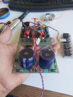
Going back to your Amp problem, could you let us know what the voltage of the main DC reservoir capacitors was, I don't think it is visible on your images.
Maybe knowing the voltage and making some assumptions about current and possible the half wave bridge 5402 diodes etc, it should be able to back track and make some presumptions?
We always had a useful discussion and remember him as being a very knowledgeable and affable man.
Going back to your Amp problem, could you let us know what the voltage of the main DC reservoir capacitors was, I don't think it is visible on your images.
Maybe knowing the voltage and making some assumptions about current and possible the half wave bridge 5402 diodes etc, it should be able to back track and make some presumptions?


Could you also let us know what coloured wires went where, primary and Secondary was there four primary wires, with two joined together at the OV point. Also how was the earthing arrangement, was the position between the two capacitors linked to the chassis metalwork.
Hi again 😊
Well there are 4 wires in secondary windings.
Purple goes to half rectification and no1. main capacitor +
Black goes to half rectification and no2. main capacitor -
Green and white are I guess centered taped and goes to pcb ground.
We have 4 wires in primary winding also.
I I'm pretty sure that only orange and grey went to mains switch as it seems in the photo. All wires from primary went through a black sleeve to the main switch and was really stretched.
The earthing was only in pcb and not at all from 0v between the capacitors to the metalwork.
If you can't find anyone to make a measurement for this model, then your best course of action might be to google all the transistors and check their maximum VCE ratings. Then decide on a reasonable margin and set it a bit lower. You can cross-check these numbers with the electrolytic capacitor voltage ratings to make sure your calculations aren't way off.
As per Osvaldo de Banfield advice.
I am thinking somewhere between 18-25V per secondary winding to keep within the 50Vdc rating of the reservoir caps.
3.5Amp fuses in each power rail suggests to me that you may only need 2-2.5A secondaries, with the caps providing the momentary peak current demand. 150VA should do it. Find a decent transformer/ PSU/amp design textbook and do the calculations instead of my estimations.
You will also need to weigh the original Tx and measure diameter and height and compare current manufacturers data sheets to match dimension's so as to get it to fit the original case if that's what you want. You may have to compromise a bit on Voltage and current ratings to find one that fits.
- Home
- Amplifiers
- Solid State
- Moth 30 Series stereo power amplifier by Stan Curtis