Hi all
I am needing to make some simple two-way crossovers for car 2-way component speakers, and am struggling to find the right inductors, so I am asking for advice about this, or suggestions about making some myself.
The speakers are Fli Integrator Comp 5 - a 5 inch single cone bass/mid plus a 1-inch tweeter. But they only came with one crossover. Initially I thought to simply duplicate this crossover to have a pair, but this crossover is basically just a 5.6uF non-pol cap in a box.
But - before I did this - a brief check with a crossover calculator had me questioning this 5.6uF cap choice by the manufacturer...
The drivers' resistance are - woofer - 3.4ohm and tweeter - 3.4ohm - so a 5.6uF cap in series with the tweeter gives a crossover of 8350Hz!
If this cap value was calculated on the basis of the tweeter being a nominal 4ohm, then the crossover would be 7100Hz (still too high).
(Apologies in advance - I am a newcomer to crossovers...)
Anyhow - basically I need to make crossovers for these two-way speakers. I can use online calculators to arrive at component specs, and source the caps and 5-10w resistors for l-pad attenuation of the tweeters if necessary - but I have questions about the inductors including what types, and what wire thickness for a tweeter vs woofer inductor, availability, and whether to make my own.
But first - what is the recommended crossover frequency for these, without exposing the tweeter to lower frequencies that might damage it?
For 1st order Butterworth, this looks reasonable...
Tweeter 3.4ohm, Woofer 3.4ohm
Tweeter - C1 = ~10uF,
Woofer - L1 = ~0.12mH
Crossover = ~4635Hz
Or L-Riley 2nd order:
C1, C2 = ~4.7uF
L1, L2 = ~0.22mH
Crossover = ~5000Hz
And if tweeter attenuation if needed, 1R & 10R resistor pairing = 2.89dB attenuation, and 1R5 & 4R7 = 4.91dB - but first I need to install the speakers to see whether this is necessary.
As I said, the only thing that's stopping me here is the inductors...
Specific questions would be...
With inductors, what would be the typical copper wire thickness for a tweeter or woofer inductor? The woofer/mid I have says '75W RMS' on it, and the tweeter - nothing written on it but it will be much lower than this - probably less than 10watts? So no doubt, this could be a much thinner-gauge inductor.
And - is it always air-core for crossovers - not ferrite core - whether it's the high pass or low pass inductor?
If I know the gauge of enamelled wire to buy, what's to stop me rolling my own? What sort of lengths would I be looking at?
I have a component tester which does inductors.
At the moment, I would be happy to just do the 1st-order crossover to get it up-and-running, and if that doesn't sound right, try a L-R 2nd later. Therefore I'd need 2 x 0.12mH inductors. Though I understand that the L-R 2nd-order might give more protection, given that car speakers sometimes get pushed to distortion to compete with road noise etc.
Any suggestions or thoughts greatly appreciated.
Thanks
You will find the online calc's will not give you exactly whats predicted, because a speaker isnt a constant ohm load it varies greatly with frequency.
Pretty much need to measure the ohm load with a frequency sweep(ZMA is the file name) and also a frequency sweep graph(FRD file)and then input that into a crossover simulator and adjust component values to suit... its a can of worms and lots of traps n pitfalls for the uninitiated.
Some speaker manufacturer's will have these measurements available but virtually zero car audio brands will, purely because a car environment is so unpredictable and results vary so much that passive crossovers are extremely difficult to get right even for the experts... this is why going full active crossovers is so popular in the car scene.
Rolling your own inductors probably isnt worth it unless you do it very often as the windings need to be quite accurate, there's oodles of off the shelf options and custom values can be had by unwinding and measuring.

Sorry to say, you are dead wrong (edit, "L",not Harry72!).
Any simple x-over calculator is complete waste of time and money. Please accept this as a fact, not an opinion.
The resistance of a speaker (most) changes with frequency. As your tweeter may have 10 ohms around 3500Hz, the 5uF cap could be spot on.
If you want to calculate the acoustic x-over frequency with a computer, you have to enter driver parameter and the measured frequency response in it's location. In your case, in the car. Then there are programs that can show you what values do what.
As an alternative, measure the speaker in the car while changing (reasonable) component values.
The bad thing , building an x-over is not an art you learn in a week. Any new component will effect the previous one. So if you add a resistor for level matching, the caps and coils you found to match, will change... can be frustrating.
Please do not insist on ways around this, there are none. I know, you will not believe, as any beginner thinks "any idiot can do it, so I'm perfectly qualified". Nope.
Measure the frequncy response and you will see that all your calculations are complete nonsese. Best they can do is to protect your tweeter from burning up, but not for sure. To be honest, the best way to do a car stereo set-up for you is active and an equalizer or DSP. The cheapest way, too. Over time you will see I'm right. Get a measuring microphone before you do anything else.
Best advice you can get. Honestly. Good luck!
Is this what you have:
https://thebassbin.co.uk/product/fli-fi5-comp-f3-5-25-13cm-2-way-225watt-component-speakers/
Technically, the previous replies are correct but it's been done that way (calculators) for millions(?) of speakers. It will generally get you close enough.
To make the calculations more likely to be accurate, you would likely need impedance compensation networks, Zobels... to compensate for the changing impedance across the audio spectrum. There is software that will calculate these networks but you need MANY electrical/mehanical parameters from the speakers which you likely don't have.
Does the amplifier you're having for these speakers have a built-in crossover?
Are you going to drive the mid and tweeter from the same channels?
Calculating x-overs like you say is done for thousands of speakers that do not even reach a fraction of their potential sonic potential.
It can be used to prevent the tweeter from too much power, that is all.
You can get a way in a three way speaker with just two parts, two capacitors in front of tweeter and midrange. How may percent distortion and what kind of response you get is very interesting in such a case. Take such speakers and construct a "real" x-over and you will not recognize the speaker any more. Done multiple times, well documented.
Many old "legendary" speakers sound simply ill today, name JBL, Electro Voice etc. With a matching x-over, done with today's measuring tools, they often show their real potential.
Why do you ignore such facts? Not anyone can construct a good x-over, but that does not indicate you do not need it.
Many people can take an knife and cut a hole into your belly, does that meant they can successfully remove your appendix and make you stay alive?
Please correct me if this method won't work to find or confirm a driver's impedance Z at a particular frequency F using only a free Android APP Frequency Sound Generator. First guesstimate Z, build a standard 1st-order XO and connect both L and C in parallel to the driver +. Play tone sweep through the XO region around F and listen with driver axially pointed at the ear but from an angle front-L/R. If flat at F then Z is confirmed. If bump at F then impedance is actually higher (passes more); if dip at F then impedance is lower (filters more). Degree of peak/valley indicates how far off.
I use simplified formulae (within 0.5%) to calculate 1st-order XO and notch filters (which the above is), in my head.
LPF ~ 160hz*Z/mH
HPF ~ 160khz/Z/uF
notch F center ~ 5khz/sqrt(mH*uF)
(independent of Z)
I'm not certain the "notch" would end up null (help please). But if two identical drivers are used above, one LP and the other HP, they ought to sum to flat (1st-order XO).
Last edited:
If you would start practical, serious speaker design, you would instantly see that this theoretical stuff doesn't work. Not even a little.
If you tell anyone "these calculators are not the best, but may be used", this is simply not true. This is comparable to tell someone who's got a drivers license he may, for short distances, be able to fly a helicopter. The result in both cases will be a very bad accident.
If you want to build an x-over in a simulation, you need measurements of the speaker in it's final position.
The normal, industry standard measured frequency response is not even near that what you find on a speaker baffel or in a car.
Using this actual data you can then feed some advanced programs, together with the drivers parameters. Now you can start to simulate a working x-over in theory that will match 80-95% of the reality. Even getting this input right needs quite some practice and deep understanding of how acoustics work.
Then you measure again and start listening to the result. Such a process can take month and still give no satisfying result, as sometimes chassis simply don't match up.
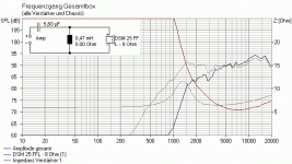
The picture shows the result of a serious simulation
If you tell anyone "these calculators are not the best, but may be used", this is simply not true. This is comparable to tell someone who's got a drivers license he may, for short distances, be able to fly a helicopter. The result in both cases will be a very bad accident.
If you want to build an x-over in a simulation, you need measurements of the speaker in it's final position.
The normal, industry standard measured frequency response is not even near that what you find on a speaker baffel or in a car.
Using this actual data you can then feed some advanced programs, together with the drivers parameters. Now you can start to simulate a working x-over in theory that will match 80-95% of the reality. Even getting this input right needs quite some practice and deep understanding of how acoustics work.
Then you measure again and start listening to the result. Such a process can take month and still give no satisfying result, as sometimes chassis simply don't match up.
The picture shows the result of a serious simulation
Attachments
This isn't a PHD thesis. He's likely working with a $40 set of components that are going to be installed in a car with acoustics that are far from perfect. If he wants to learn the fine details (which can take years), that's fine but let's help him on the level that he's on, for now.
Let's see what he says he's working with.
Let's see what he says he's working with.
OK, then the best he can do is to keep the 5.6uF capacitor and call it a day. It is perfect for his kit and an in car installation.
The woofer is build to run without an x-over. He will not gain anything from extra parts,
The woofer is build to run without an x-over. He will not gain anything from extra parts,
Thanks Perry - I was just writing...
Much appreciation to all for your comments.
Yes - I understand now that crossover calculators are a crude guide, and it sounds like a lot of people use them but live with non-optimised crossover setups.
I am also seeing that people here and elsewhere recommend using active crossovers or separate amp channels set up for individual driver frequency ranges. (I have various other smaller car amps and DC stereo amps lying around - one of which could be set up to drive tweeters? The main amp is 4 x 50W RMS, the speakers rated 75W RMS, so the tweeter amp could probably be 15-20W RMS per channel?)
Turbowatch2 pointed out that the resistance of a speaker goes up with higher frequencies, and that maybe the 5.6uF cap is correct - perhaps an example of crossover calculators getting it wrong. And after all - presumably a company who designs and sells speakers knows about speaker design(!), even if they are cutting costs when it comes to crossovers in this instance.
So - quite possibly I could just buy another 5.6uF cap and get by doing the absolute minimum.
But this problem has caused me to do some research about crossovers and speakers, and I am open to going further with this - either some passive crossovers or running the tweeters from their own amp channels.
Therefore - if I can arrive at cap and inductor sizes which will generally sound ok - and hopefully protect the speakers somewhat - I would be interested in making some passive crossovers - 1st or 2nd - as long as I can get the inductors. If the crossover calculators just spew out BS - there must be a way to arrive at cap and inductor sizes even if we don't have the data on these speakers.
Or else - if a better option would be tweeters driven by their own amp - then - I would request pointers about what this might involve - presumably a pre-amp/buffer circuit between the head unit and amp which narrows the bandwidth specifically for tweeters. And this would obviously allow the tweeters to be attenuated without L-pad resistors.
Any thoughts appreciated.
Maybe you're rightOK, then the best he can do is to keep the 5.6uF capacitor and call it a day. It is perfect for his kit and an in car installation.
The woofer is build to run without an x-over. He will not gain anything from extra parts,
Is this what you have:
https://thebassbin.co.uk/product/fli-fi5-comp-f3-5-25-13cm-2-way-225watt-component-speakers/
Does the amplifier you're having for these speakers have a built-in crossover?
Are you going to drive the mid and tweeter from the same channels?
The 'resistance' that you read with an ohm meter is the coil resistance. Many 4 ohm (impedance, not resistance) speakers will read a lower resistance. You calculate with the rated impedance.
Hi Perry
Yes - those are the speakers - FLI Comp 5.
The amp I have is a 4 x 50W RMS that outputs standard front and rear stereo pairs - it doesn't have built-in crossovers. The front stereo pair are to be used for the FLI 2-way speakers (the rear channel pair go to their speakers).
As I was saying, I have several smaller 12-14V DC stereo amps up to 20W RMS per channel, one of which could be installed and used to drive the tweeters. None of these have any crossovers built-in, but presumably high-pass filters could be inserted - before the amp, where 'tone' circuits would normally go?
After following discussions on this thread, I read a bit about speaker impedance curves - that impedance rises as the frequency gets higher due to voice coil inductance (is this correct?) - and the way this can screw around with crossover values at different frequencies. I looked online at several speaker impedance curves - as examples - and could see that they often sat around ~4ohms along much of their spectrum, then headed up towards ~6ohm once over ~4-5000Hz. The 5.6uF cap that FLI use as the high-pass filter in these speakers makes a bit more sense with this in mind (though it seems a bit 'conservative').
Or should I just do as Turbowatch2 suggests and use 5.6uF caps and be done with it?! I could just install it like this, and if it sounds terrible - or if the tweeters need attenuation - I could rethink it then?
Thanks again
You’ll be fine with the 5.6uf cap if you don’t overdrive the amp into clipping. The power rating of that speaker is a little optimistic! Figure 50 watts maximum for the woofer and 20 for the tweeter. You’re not splitting atoms here so just a cap will work. Are there better ways of doing it? Yes. Is it worth it? Probably not. If you want to jazz it up buy film caps rated 50 volts or higher at 5.6uf. They sound a little better and don’t dry out in the heat of a car. If it sounds bad then come back here. If you hear distortion turn it down before you fry a speaker!
Make/model of the 4 channel amp?
Make/model of your head unit?
"The front stereo pair are to be used for the FLI 2-way speakers (the rear channel pair go to their speakers)."
^^^ Do you have two coaxial speakers as well as the FLI comp 5 separates? If not, rephrase that, referring to the tweeters as tweeters and the 5.25" drivers as such.
The impedance will increase at higher frequencies but the impedance varies, especially at the resonant frequency of the speaker. For larger speakers, the enclosure can greately affect the resonant frequency.
Thanks Perry
Sorry I didn't give details of the car stereo and amp because it seemed like extraneous detail, and it's a bit long-winded...
I was wondering whether it was possible to take the Front L&R signals from the head unit, and duplicate them - with a passive or buffered splitter - so one audio pair could go into the PA-200 Front L&R, and these drive the FLI 5.25" as a low-mid drivers. And the other audio pair could go into another amp - which could be say 20W RMS per channel - with high-pass filtering pre-amp - and it could drive the tweeters.
With this idea, the two basic things I don't yet know - but once I did I could get on with making them - would be:
Thanks for looking at this. Any suggestions appreciated.
Sorry I didn't give details of the car stereo and amp because it seemed like extraneous detail, and it's a bit long-winded...
- The head unit is a 1992 Volvo TD-603 radio-cassette, where the cassette has been replaced by a Bluetooth receiver, and the unit has been refurbished. Unless I'm mistaken it only outputs Front L&R, Rear L&R as line/pre-amp level - there is no speaker outputs from it.
- The amp is a circa-2005 Volvo PA-200 (Volvo # 30752259) which is very simple with just 4 x TDA7294 amp chips and a power supply (transformered up to 50v dc single rail from memory) and not a lot else in its case.
- The rear channel pair from the amp go to co-axials in the back.
- The front channel pair from the amp: these are what drive the two speakers of the FLI Comp5: the 5.25" woofer/mid & the tweeter (and to be clear no other speakers).
I was wondering whether it was possible to take the Front L&R signals from the head unit, and duplicate them - with a passive or buffered splitter - so one audio pair could go into the PA-200 Front L&R, and these drive the FLI 5.25" as a low-mid drivers. And the other audio pair could go into another amp - which could be say 20W RMS per channel - with high-pass filtering pre-amp - and it could drive the tweeters.
With this idea, the two basic things I don't yet know - but once I did I could get on with making them - would be:
- What's the best way to split/duplicate line-level audio signals so one becomes two: a passive y-splitter, or active no-gain buffers? Apparently a passive y-splitter would be ok but I'm still not sure why this doesn't degrade the signal somehow.
- If an amp is set up for driving tweeters, I'm assuming this involves installing a filter circuit pre-amp - like the high-pass filter part of this?...
Thanks for looking at this. Any suggestions appreciated.
The signal doesn't degrade with a y-cable because the output impedance of most preamp signals is very low (100 ohms or less) and the input impedance of most amps is very high (10,000 ohms, typical).
Does your head unit have signal or DC voltage on the negative preamp level wire?
The amp will be able to drive more clean power to the tweeters if it has a filter (crossover) to filter out the low frequencies.
The passive crossover shown would help but an active crossover would typically be a better option. The passive circuit may work for your amp but it wouldn't for most OEM systems because they use a balanced output (biased to 1/2 B+) which would drive 1/2 B+ plus the negative speaker wire signal to the shield ground of the amp.
Thanks again Perry
Excuse me if I'm playing catch-up - this is all a learning curve for me - thanks for your patience here...
OK - so I can see what an active crossover is - as opposed to the previous message where I stumbled on a passive pre-amp crossover with Google. Something like this?...
https://sound-au.com/project08.htm
Is there a popular DIY design available for an active 2-way crossover, (or even a kit/pcb) which is set up with the right impedances and levels etc so it can be inserted into a chain between the output of a head unit and the inputs of standard power amps? Plus a power-supply solution, made a bit harder by being in the context of a 12-14vdc environment. The crossover itself looks like it uses fairly common components - a few op-amps, caps etc.
Ummm - apologies - some stuff I know, most stuff I don't. Is there a measurement I can take on the actual unit to answer this? I think I kind-of understand what this and quote below are about. Could you say just a bit more about this, so I can see more about what you're referring to?
Thanks again
Excuse me if I'm playing catch-up - this is all a learning curve for me - thanks for your patience here...
OK - so I can see what an active crossover is - as opposed to the previous message where I stumbled on a passive pre-amp crossover with Google. Something like this?...
https://sound-au.com/project08.htm
Is there a popular DIY design available for an active 2-way crossover, (or even a kit/pcb) which is set up with the right impedances and levels etc so it can be inserted into a chain between the output of a head unit and the inputs of standard power amps? Plus a power-supply solution, made a bit harder by being in the context of a 12-14vdc environment. The crossover itself looks like it uses fairly common components - a few op-amps, caps etc.
Does your head unit have signal or DC voltage on the negative preamp level wire?
Ummm - apologies - some stuff I know, most stuff I don't. Is there a measurement I can take on the actual unit to answer this? I think I kind-of understand what this and quote below are about. Could you say just a bit more about this, so I can see more about what you're referring to?
The passive crossover shown would help but an active crossover would typically be a better option. The passive circuit may work for your amp but it wouldn't for most OEM systems because they use a balanced output (biased to 1/2 B+) which would drive 1/2 B+ plus the negative speaker wire signal to the shield ground of the amp.
Thanks again
Some OEM head units have a balanced output where both the positive and negative signal lines are biased to 1/2 of the supply voltage (typically between 9v & B+). You need to know this when connecting to other components.
Other OEM systems could be using a more standard signal with one wire for signal and the other at 0v (ground). This is more what the standard aftermarket head units use.
You can measure the DC voltage on the negative signal line to see if it's 0v or something near 6v. The signal line should also be very near 0v but leakage through capacitors may let it float slightly.
For a crude passive crossover, you could go into the amp you're using for the tweeters and replace the input coupling capacitor with a much smaller value. Depending on the input circuit, you may have to also install a loading capacitor just after the capacitor to get the capacitor to act as a filter. This is crude but will help block the bass from the amp. I'd still keep the inline capacitor in the speaker line with the tweeter.
What is the 20w/ch amp that you have.
The crossover on the ESP site would likely work well but you need 2x the components in the diagram.
The split supply can be produced in several ways. You can buy small switching power supplies from ebay. It's not difficult to make your own. The most difficult part is sourcing a suitable core and that's not too difficult. A lot of people make the mistake of using an inductor core. They look the same but have very different properties.
- Home
- General Interest
- Car Audio
- Crossover inductors - roll-yer-own