A 200V PS for use with TV Horizontal Sweep Tubes
Surfing around on DIY we see quite a few requirements to supply the screen of this or that sweep tube. Here is my take on something that works reasonably well. And the circuit can form the starting point for others.
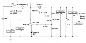
I selected a 6EM7 for this exploration, it can dissipate 11W. The H-K insulation is good for 200V allowing the heater to operate from the common 6.3VAC heater supply. And there is a high mu triode in the same bottle that can be used as an error amplifier. And it looks nice, important for those who are building their work of art.
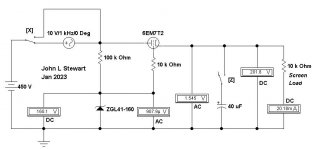
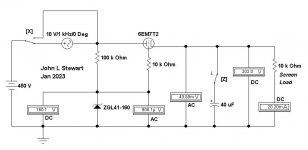
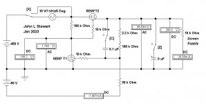
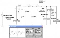
The simple simulation without an error amp shows a very basic 200V G2 supply. With 450V B+ the drop of 250V supplying 20 mA results in dissipation of ~5W. This using a Zener as the reference, it could just as well use a VR tube.
The Sim has 10VAC interfering signal that can be switched in series with the 450V DC to fill in for ripple on the raw B+. The action of the 6EM7 T2 is to reduce this by its 1/mu. If the 6EM7 T2 were a perfect triode the resultant ripple at the output would be 1.85VAC. It isn’t. So AC from the PS ripple is 1.545V. Connecting a 40 microF cap across the output reduces the ripple to ~50 mV.
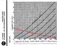
The regulation to load changes can be estimated by treating the output of the circuit as a cathode follower, ( rp + Rsupply ) / ( mu + 1 ). At 20 mA rp is not 750R as we see at the top of the data sheet. For the brave you can go to page 13 of the attached data. There you will find the required information, a rather steep curve. The triode model in the simulator used does not do well here!
The simple 200V supply works but will do much better with some gain applied to the error.
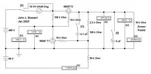
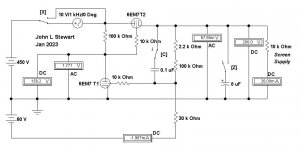
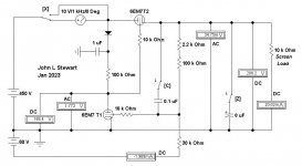
Using the 6EM7 T1 triode as the error amp requires a negative supply. This is something that is easily fixed by providing a simple, stable negative voltage, supplying just the reference. Several folks mentioned they had a PT with a 60v tap, so that is a convenient place to start. There are several ways to get the negative reference voltage. That is something to be looked at later.
Now the 60V reference is compared to a fraction of the output voltage, in this case simply
~ 30 / ( 30 + 102.2 ) ……………………or about 23%
When writing equations for Reg PS performance this fraction is often referred to as K. A large K is preferable, that could be achieved here with a 150V reference. Something to keep in mind.
With the error amp in the circuit the ripple on the output is reduced to ~1/4 Volt. By connecting a small cap from the 200V rail to the error amp grid the factor K becomes One. And the ripple at the output is further reduced. And finally an electrolytic across the output to supply any large surges of G2 current in amp it works with.
In the next exciting episode various ways to get a good negative reference without pain, suffering & agony!!
Surfing around on DIY we see quite a few requirements to supply the screen of this or that sweep tube. Here is my take on something that works reasonably well. And the circuit can form the starting point for others.
I selected a 6EM7 for this exploration, it can dissipate 11W. The H-K insulation is good for 200V allowing the heater to operate from the common 6.3VAC heater supply. And there is a high mu triode in the same bottle that can be used as an error amplifier. And it looks nice, important for those who are building their work of art.
The simple simulation without an error amp shows a very basic 200V G2 supply. With 450V B+ the drop of 250V supplying 20 mA results in dissipation of ~5W. This using a Zener as the reference, it could just as well use a VR tube.
The Sim has 10VAC interfering signal that can be switched in series with the 450V DC to fill in for ripple on the raw B+. The action of the 6EM7 T2 is to reduce this by its 1/mu. If the 6EM7 T2 were a perfect triode the resultant ripple at the output would be 1.85VAC. It isn’t. So AC from the PS ripple is 1.545V. Connecting a 40 microF cap across the output reduces the ripple to ~50 mV.
The regulation to load changes can be estimated by treating the output of the circuit as a cathode follower, ( rp + Rsupply ) / ( mu + 1 ). At 20 mA rp is not 750R as we see at the top of the data sheet. For the brave you can go to page 13 of the attached data. There you will find the required information, a rather steep curve. The triode model in the simulator used does not do well here!
The simple 200V supply works but will do much better with some gain applied to the error.
Using the 6EM7 T1 triode as the error amp requires a negative supply. This is something that is easily fixed by providing a simple, stable negative voltage, supplying just the reference. Several folks mentioned they had a PT with a 60v tap, so that is a convenient place to start. There are several ways to get the negative reference voltage. That is something to be looked at later.
Now the 60V reference is compared to a fraction of the output voltage, in this case simply
~ 30 / ( 30 + 102.2 ) ……………………or about 23%
When writing equations for Reg PS performance this fraction is often referred to as K. A large K is preferable, that could be achieved here with a 150V reference. Something to keep in mind.
With the error amp in the circuit the ripple on the output is reduced to ~1/4 Volt. By connecting a small cap from the 200V rail to the error amp grid the factor K becomes One. And the ripple at the output is further reduced. And finally an electrolytic across the output to supply any large surges of G2 current in amp it works with.
In the next exciting episode various ways to get a good negative reference without pain, suffering & agony!!
Attachments

I made several series regulators with 6EM7, 6FM7, 6FD7 and 13FD7 vertical deflection tubes, again, not one but several.
10K stoppers are completely useless and in fact the can produce a bad working of the regulator. Take the voltage amplifier anode load from the output side via a 100K anode load, that in turn will put this resistor across grid and cathode of pass triode. It is highly recommended.
If you have interest in this regulators, I may suggest you future improvements to the basic configuration. I don't do it here because ussualy my posts seems to be transparent and nobody cares them. For example, post #10 at:
https://www.diyaudio.com/community/...able-regulator-for-tubes.394757/#post-7242327
Last edited:
Oswaldo's advice in the PS Thread as follows
If you like to play around voltage regulators/stabilizer, there is a pair of things you want to know:
1.- Convert the voltage or error amplifier into a cascode, tube, JFET or MOSFET (BJT has the base current limitation and I personally dislike them as voltage amplifiers). Use the grid/gate of the bottom to feed back a sample of the output voltage to close the regulation loop as normal. Then feed forward a sample of input voltage to the top grid/gate. There will be an optimal top input value for what the ripple rejection is almost perfect (infinite), above which ripple has negative polarity repect to the input. I made it with real tubes and this behaviour is predicted as old as 1939, 8 decades ago and still in use. The two bulb regulator depicted use this principle, with some refinents.
2.- In a normal series regulated supply there is a tendency of it to become inductive looking backwards from output terminals into the regulator. As both the series pass and the error amplifier's gain decline with increasing frequency, its output impedance increases as result. Thus it's like an inductor. Thus, there is always an output capacitor value in which the PSU breaks into oscillations stimulated by load currents or the intrinsic noiser elements in the PSU itself. I discovered it in an article from Philips Technical Review about the 40's of the past century.
---------------------------------------------
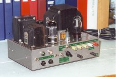
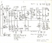
Both very good points & included in this lab PS I built for myself circa 1960.
One mistake often made is too large a cap on the Reg PS B+ output lead. That can lead to oscillation.
I built many Reg PS, most with 2-stage error amps but never had an oscillation problem.
If you like to play around voltage regulators/stabilizer, there is a pair of things you want to know:
1.- Convert the voltage or error amplifier into a cascode, tube, JFET or MOSFET (BJT has the base current limitation and I personally dislike them as voltage amplifiers). Use the grid/gate of the bottom to feed back a sample of the output voltage to close the regulation loop as normal. Then feed forward a sample of input voltage to the top grid/gate. There will be an optimal top input value for what the ripple rejection is almost perfect (infinite), above which ripple has negative polarity repect to the input. I made it with real tubes and this behaviour is predicted as old as 1939, 8 decades ago and still in use. The two bulb regulator depicted use this principle, with some refinents.
2.- In a normal series regulated supply there is a tendency of it to become inductive looking backwards from output terminals into the regulator. As both the series pass and the error amplifier's gain decline with increasing frequency, its output impedance increases as result. Thus it's like an inductor. Thus, there is always an output capacitor value in which the PSU breaks into oscillations stimulated by load currents or the intrinsic noiser elements in the PSU itself. I discovered it in an article from Philips Technical Review about the 40's of the past century.
---------------------------------------------
Both very good points & included in this lab PS I built for myself circa 1960.
One mistake often made is too large a cap on the Reg PS B+ output lead. That can lead to oscillation.
I built many Reg PS, most with 2-stage error amps but never had an oscillation problem.
Attachments

Also this cap being too large cause a large time to the output voltage to reach its final value. I use usually 1Sec time constant and no much more.
Reg PS Ref Supply…………………….Solution A Using 60V Tap on the Amp PT
The half wave rectifier circuit does not provide enough voltage to allow proper smoothing for the required reference voltage. Why not a doubler, that is what we have here. Under load conditions there is 112V available & proper smoothing is possible. The 62V Zener provides a relatively clean reference of the voltage required, less than 3 mV ripple p-p. We are not building a precision PS!
The half wave rectifier circuit does not provide enough voltage to allow proper smoothing for the required reference voltage. Why not a doubler, that is what we have here. Under load conditions there is 112V available & proper smoothing is possible. The 62V Zener provides a relatively clean reference of the voltage required, less than 3 mV ripple p-p. We are not building a precision PS!
Attachments
Excellent thread, thank you guys! I was wondering whether going solid state or tube for a 200V regulator, now I'm almost 100% sure I will go with E/PCL8x tubes. Time to build a prototype.
Does putting a zener diode in the triode’s cathode just NOT work here for some reason? Noise perhsps?
You could try that, only to find there is not enough plate voltage left
for the error amp to work properly. Better to just make a negative supply,
real easy to do. 👍
for the error amp to work properly. Better to just make a negative supply,
real easy to do. 👍
I've done some simulations with a PCL85, a TL431 tuned for 20V on triode's cathode, looks fine for currents up to 60mA. Need to try it for real though.
Personally I don't mix tube and ss. Thus in most of my circuits, I make a negative 150V in order to strike a neon lamp and use it as reference. The amplifier cathode is grounded directly (in some instances a high mu triode or a pentode) and the regulator behaves more like an anode follower or see/saw circuit. But as cathode is grounded, no degeneration occurs.
I do mix a bit of sand with tubes. Mostly in rectifiers and CCDs. Never used a tube-based regulator, but not having a heatsink and sharp voltage breakdown is enticing.
A negative reference I suppose is necessary to generate g1 bias, so it would be available. My thinking was you’d probably be trying to drop a common supply voltage of 340 (rectified 240) to 450 volts down to 200 - or maybe even 125 for the big boys, which would leave you plenty of plate voltage after a 68 volt zener was stuck in there. Trying to make 0 to 400V lab supply, or trying to drop 250 down to 200 you’d want that negative reference for sure.
I usually just use zener stacks with an RC filter after it - then go into a mosfet. Yeah, it takes 15 seconds to charge fully but doesn’t seem to hurt anything and can get really quiet when you need it (for preamp stages). But there is an attraction to getting rid of all transistors, and knowing that you won’t get some second-breakdown effect in the mosfet-du-jour.
You guys try triode-strapping the pentode from say a 6LU8 for the pass tube? I have more of these on hand than I do dual triode vertical osc/amps, and even more of the triode-plus-video-amp’s (if 50-100 mA peak screen current is enough).
I do that in my simulations...
You guys try triode-strapping the pentode from say a 6LU8 for the pass tube? I have more of these on hand than I do dual triode vertical osc/amps, and even more of the triode-plus-video-amp’s (if 50-100 mA peak screen current is enough).
There are an infinity squared number of possibilities for this kind of circuit.Does putting a zener diode in the triode’s cathode just NOT work here for some reason
Trying to get something simple into one glass bottle where the circuit does not defy the
Laws of Gravity or anything else creates some problems. A pentode such as a 6AU6 for the error amp
allows getting to lower regulator output voltages & works well. Then to find all that in one bottle!
If possible I prefer VR toobs. Zeners sometimes come with a rather high voltage vs temperature problem
Later I'll shew some tricks I've used but other things need doing here at the moment.
The TL431 needs around 0.4mA. Is something to keep an eye on, yes.Remember that most LM431 needs not less than 5mA to operate properly.
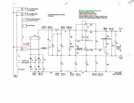
Here be the 6EM7 PS G2 Reg using a Zener in the cathode of the error amp.
K looks good at ~0.31. There is 388V (450-62) available for the error amp. The 100K loadline terminates at 3.88 mA.
The Sim shews 156V on the plate, with 62V on the cathode, T1 sees only 94V.
Normal operation looks marginal at best. Work for some & not others,
A negative supply gets us to were we need to go.
I'd planned to push this a little further down. There are several here on DIY using 2E24, 2E26, 815, 829B & 832A.
Need to get down to at least 100V to cover all applications. One of the lab supplies I built for general use
covered 100-200V. That was circa 1960. I used a negative supply on silicon diodes from the same supply as the B+. 👍
Attachments
- Home
- Amplifiers
- Tubes / Valves
- A 200V PS for use with TV Horizontal Sweep Tubes