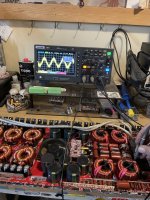
Hey all, so the 4 relays on an Orion HCCA 8000.1D are not switching on after amp boots up, everything else is confirmed working/switching properly, and I see my 50Hz input signal just before relays, so while trying to figure out what is going on I realized I do not even tech I ally know what the relays are exactly for and/or what conditions must be met for the relays to a switch on. I have seen relay failure before but all 4 at once?
If anyone can help shine some light as to what the Speaker Output Relays are for, the conditions needing to be met for switch on, and other other pertinent info would be greatly appreciated. Ty 🖖🏼
If anyone can help shine some light as to what the Speaker Output Relays are for, the conditions needing to be met for switch on, and other other pertinent info would be greatly appreciated. Ty 🖖🏼
Attachments
Try to resolve if the relay or its driver are faulty or it is really protecting the amp (DC at output, overload, etc.).
It isn't a good idea to keep flammable liquids at the workbench. Keep them far from possible sparks or fire. For your own safety.
It isn't a good idea to keep flammable liquids at the workbench. Keep them far from possible sparks or fire. For your own safety.
I came across this in my interwebs searching,
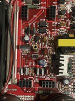
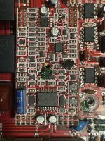
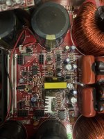
“There is a relay control circuit which can be a nightmare to track an issue in. Most cases the issue is on the power supply card. There is a delay circuit that switches a transistor under teh power supply card. This is where I hook up header cables to set the card off to the side to probe the areas under the card while on.”
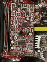
First 2 pics are the power supply riser card and underneath it. Pics 3&4 are matching Output riser cards. There was quite a bit of vibration damage on this board on the metal rails, FETs, etc, which are all now resoldered but I can def see how the “relay circuit”? Could be hit with something funky. Never came across a problem like this before.
“There is a relay control circuit which can be a nightmare to track an issue in. Most cases the issue is on the power supply card. There is a delay circuit that switches a transistor under teh power supply card. This is where I hook up header cables to set the card off to the side to probe the areas under the card while on.”
First 2 pics are the power supply riser card and underneath it. Pics 3&4 are matching Output riser cards. There was quite a bit of vibration damage on this board on the metal rails, FETs, etc, which are all now resoldered but I can def see how the “relay circuit”? Could be hit with something funky. Never came across a problem like this before.
Attachments
No I did not, and from what I know I am the first one into this amp’s guts, but it does look like it was “modified” or the like after initial manufacturing. It is reading 991.
I checked the PS driver board from an HCCA 5000.1DSPLX and it seems identical and it is also a 1k resistor @ R538
I checked the PS driver board from an HCCA 5000.1DSPLX and it seems identical and it is also a 1k resistor @ R538
Last edited:
Did you confirm that that resistor was within tolerance? It sometimes goes out of tolerance and won't let the relays engage.
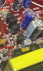
Yes, it is within tolerance. Reading at 991-995 last I checked, I’m assuming the connected components, which look to be JFETs, are responsible for the relay circuit? I’ll test in the area on what’s connected via trace to see if I can see anything off 🙂 Ty Perry!
Q531 & Q532, which are on each end of that resistor, are probing “good” with a DMM. Think I might just probe the whole board 😅
What's the DC voltage on all terminals of IC561 on the PS drive board?
Pin 1:
Pin 2:
Pin 3:
Pin 4:
Pin 5:
Pin 6:
Pin 7:
Pin 8:
Pin 1:
Pin 2:
Pin 3:
Pin 4:
Pin 5:
Pin 6:
Pin 7:
Pin 8:
IC561 / LM393
Pin 1: 11mv
Pin 2: 4.9v
Pin 3: 2.8v
Pin 4: 6mv
Pin 5: 8mv
Pin 6: 5v
Pin 7: 3mv
Pin 8: 14.1v
Shouldn’t I be seeing waves on this IC? I haven’t dug into an amp in over 2 months, almost feels like I forgot some basics 😅 but I know I should be seeing some waves on this IC, triangle and square actually, right?
There are no waveforms on this IC. It's pure DC. It's used for the thermal and over-current protection.
DC voltage on all 3 terminals of Q531 and Q532? Black probe on the primary ground.
Q531
Base:
Collector:
Emitter:
Q532
Base:
Collector:
Emitter:
DC voltage on all 3 terminals of Q531 and Q532? Black probe on the primary ground.
Q531
Base:
Collector:
Emitter:
Q532
Base:
Collector:
Emitter:
Ahh ok, I think I got the Output mixed up with the Power Supply regarding what has waves and doesn’t 😅
Q531
Base: 14v
Collector: 11mv
Emitter: 14v
Q532
Base: 600mv
Collector: 7mV
Emitter: 6mv
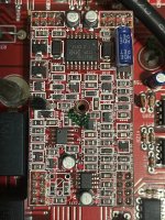
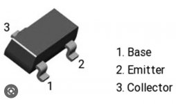
I’ve seen a few diagrams online that seem to switch around the Base, Collector, Emitter depending on which chip this is and I don’t know which exactly this Sot23 chip is (although I did find new sets of both “FR” and “BR” in my parts stash, of course not in their properly labeled bag for some reason 🤦🏼) pins are as in pic.
Q531
Base: 14v
Collector: 11mv
Emitter: 14v
Q532
Base: 600mv
Collector: 7mV
Emitter: 6mv
I’ve seen a few diagrams online that seem to switch around the Base, Collector, Emitter depending on which chip this is and I don’t know which exactly this Sot23 chip is (although I did find new sets of both “FR” and “BR” in my parts stash, of course not in their properly labeled bag for some reason 🤦🏼) pins are as in pic.
Attachments
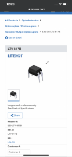
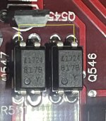
I can order some today, I do have some from a donor board I can try as well in the meantime. Pics correct for part number for Q456? Just making sure, not familiar with octocouplers 😅
Attachments
I don't have a diagram for this amp specifically. I'm looking for some reference to tell me which diagram I should refer to for this part of the circuit.
Are any of the transistors in that area marked 2N7000?
Are any of the transistors in that area marked 2N7000?
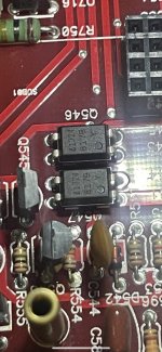
Checking between the terminals 3 and 4 of the two adjacent optocouplers (in all combinations) do you read 0 ohms between any of the terminals?
- Home
- General Interest
- Car Audio
- Class D Speaker Output Relay?