Hi Guys,
I've been using the Lampizator circuit attached to a TDA1541A DAC for about a year now. I'm very happy with the deep sound it produces and it suits my music taste which is mainly vocals and strings. Therefore I've never really tested it with a VTVM or oscilloscope to see how the FR is, I was just happy with the sound.
Out of boredom, the other day I've measured the FR and it looks way out of specs. I have 2 of these units built and both of them have the same lazy specs. Basically the curve is not flat at all with about -5db at 10KHz and -11db at 20KHz. The sound it produces doesn't really seem to reflect these number though unless my ears are getting really bad. The same numbers are shown on the VTVM and osc.
The TDA1541 has flat FR. The coupling cap is a ClarityCap.
Just looking at this circuit, does it scream crappy FR? Is there something I can do to improve the top end or that's just how this circuit works? I guess I have a case of FOMO.
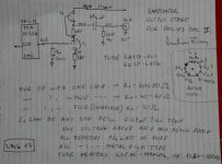
Lampizator has a couple of circuits, one with 6N1P and another with 6N2P. I'm attaching both of them as well as the power supply schematic used, I've tried both and they both have the same FR.
Thanks
I've been using the Lampizator circuit attached to a TDA1541A DAC for about a year now. I'm very happy with the deep sound it produces and it suits my music taste which is mainly vocals and strings. Therefore I've never really tested it with a VTVM or oscilloscope to see how the FR is, I was just happy with the sound.
Out of boredom, the other day I've measured the FR and it looks way out of specs. I have 2 of these units built and both of them have the same lazy specs. Basically the curve is not flat at all with about -5db at 10KHz and -11db at 20KHz. The sound it produces doesn't really seem to reflect these number though unless my ears are getting really bad. The same numbers are shown on the VTVM and osc.
The TDA1541 has flat FR. The coupling cap is a ClarityCap.
Just looking at this circuit, does it scream crappy FR? Is there something I can do to improve the top end or that's just how this circuit works? I guess I have a case of FOMO.
Lampizator has a couple of circuits, one with 6N1P and another with 6N2P. I'm attaching both of them as well as the power supply schematic used, I've tried both and they both have the same FR.
Thanks
Attachments
There's nothing wrong with liking the sound even if it's down in response above 10kHz.
It's only one octave of the 10 octaves in the audio band, and there isn't much music there to speak of anyway.
So if you like it, why do you want to chance it? Do you listen to a scope?? 😎
Jan
It's only one octave of the 10 octaves in the audio band, and there isn't much music there to speak of anyway.
So if you like it, why do you want to chance it? Do you listen to a scope?? 😎
Jan
Did you measure the FR at the input to the tube grid?
Can you show us the circuit as built with values for capacitors and resistors? And how you measured the FR?
Steve
Can you show us the circuit as built with values for capacitors and resistors? And how you measured the FR?
Steve
The DAC is on one of those boards made specifically used and commonly used by others. It comes out of China. The DAC board is attached via usb to a volumio box (streamer). Signal generator is my iphone attached to volumio via airplay.
I have used the Lampizator1 circuit attached in the first post. The values are exactly as in the diagram using a 2.2uF for the coupling capacitor. Adjusted the power supply attached to match the volt values as in the circuit.
The FR has been measured at the grid and it’s extremely flat. It was measured with vtvm and osc. Phone is at maximum volume and the signal at grid is about 70mV at 1khz.
The FR was also measured at the output behind the cap. This FR has a high end roll off of about -11db at 20khz.
LTSpice modeling shows a flat FR but I’ve learned that simulation is not very accurate, at least the with the tube circuits i’ve played with.
Let me know if you need other values.
Again, I’m happy with the sound but i’m suffering of the fear of missing out and wondering if the already amazing sound could be made even better. Also, if the input at the grid is flat shouldn’t the output be quite flat as well? I mean the circuit is quite simple.
I’ve built other tube preamps that are +/- 1db but sounds a bit bright and sterile.
There are 2 different circuits in the first post. One shows a 100 ohm resistor from input grid to ground. This does not seem correct. And one does not show a load resistor after the output capacitor. Which circuit did you use and what are the values of the resistors?
Steve
Steve
If the DAC in Post # 1 is a Current Output DAC, then a resistor of 50 Ohm to 100 Ohm may be correct.
Many Current output DACs that are not terminated by a low impedance do not have enough (Voltage) compliance to work into a high impedance load.
Just my $ 0.02
Many Current output DACs that are not terminated by a low impedance do not have enough (Voltage) compliance to work into a high impedance load.
Just my $ 0.02

Yes. What the heck is R8 for??? You are not taking-out a signal there. But there IS signal and it kicks-back through plate-grid capacitance to the active node. I wouldn't even ask SPICE. I'd put a proper bypass cap at the plate. (Or lose BOTH 22e3 (=22k) resistors because more supply voltage is lower THD.)does it scream crappy FR?

PRR, obviously i’m a nube. Would you please show on the schematic where the bypass cap at the plate would go and what size?
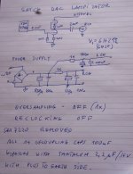
The PS schematic is from other tube amps and I thought they’re just a bunch of filters. Is there something wrong with it? The power source is a smps which can be quite noisy but it delivers 300v and 0.6A.
The PS schematic is from other tube amps and I thought they’re just a bunch of filters. Is there something wrong with it? The power source is a smps which can be quite noisy but it delivers 300v and 0.6A.
If you have another 6N2P you should try that tube as well to make sure the problem is not with the tube.
Steve
Steve
I have many 6n2p’s and 6n1p’s. Tried a few and they all have the same FR.
Do you guys see anything wrong with the circuit though?
Do you guys see anything wrong with the circuit though?
If it is NOS running at 44.1 it will, depending on how you measure it roll off to varying degrees, due to the lack of reconstruction filter.
Your second picture in your first post is fine.
I don't know where you got that "PS" plan but those 22k resistors are not appropriate for this amplifier.
I don't know where you got that "PS" plan but those 22k resistors are not appropriate for this amplifier.
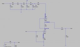
Hi . I usIng 6n1p for my dac tda1387 x8 (rpi hat). What i tested need very low resistor from grid to ground 27r and going try even less to lower output lvl . lampizator mention that , but he been using x4 with 30r .
Ive ordered 6n2p and gonna try them later .
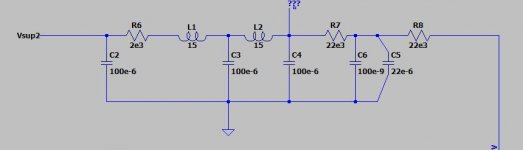
I have to double my capacitance to get rid off hum (picture). Probably doing something wrong , but cant figure out .
You using 6n2p but cathode resistors you have from 6n1p circuit 680r , but it should have 200r.
Psu im using :
Ive ordered 6n2p and gonna try them later .
I have to double my capacitance to get rid off hum (picture). Probably doing something wrong , but cant figure out .
You using 6n2p but cathode resistors you have from 6n1p circuit 680r , but it should have 200r.
Psu im using :
Attachments
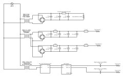
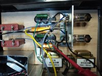
Get rid of the 15k resistors (same problem as the OP with 22k resistors). The output from the power supply (from 470uF cap) needs to go directly to the top anode in the SRPP. Also, the original Lampizator PS has 820uF after the rectifier.
- Home
- Amplifiers
- Tubes / Valves
- TDA1541 Lampizator Circuit FR Response