Hi all,
I have built Rod's discrete opamp and wanted to install it in a DAC board which contained a JRC5532 opamp.
https://sound-au.com/project07.htm
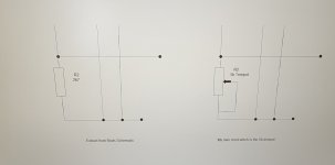
The only difference to the circuit was to replace the 2k7 resistor for a 5k trimpot, which is required to adjust for DC offset if the supply voltage varies from the schematics 20v test voltage (and the calculated 2k7 resistor) and this is wired as the attachment (bottom left section of the schematic only). Additionally, I have installed a 10uf electro on the output of the discrete as, ultimately, it will be used within a preamp.
I don't have the circuit for the DAC unfortunately but it one of those from Ebay.
The input and output voltages of the JRC5532 measured 2.5v. Which suggests the opamp is for Vref. Swapping for the discrete Opamp, the output voltages measure 5v. (5v before the 10uf electro, 0v after)
The discrete appears to be working fine but, somehow, is amplifying offset gain by a factor of 2.
Would anyone have any ideas why this would be the case? The only thing I can think of is that with the 10uf cap installed, which would explain really, but I just wanted to double check with the experts if that's OK.
Also, the 5k trimpot does not affect the output in anyway either and this was supposed to adjust offset to 0v (as an amplifier).
I have built Rod's discrete opamp and wanted to install it in a DAC board which contained a JRC5532 opamp.
https://sound-au.com/project07.htm
The only difference to the circuit was to replace the 2k7 resistor for a 5k trimpot, which is required to adjust for DC offset if the supply voltage varies from the schematics 20v test voltage (and the calculated 2k7 resistor) and this is wired as the attachment (bottom left section of the schematic only). Additionally, I have installed a 10uf electro on the output of the discrete as, ultimately, it will be used within a preamp.
I don't have the circuit for the DAC unfortunately but it one of those from Ebay.
The input and output voltages of the JRC5532 measured 2.5v. Which suggests the opamp is for Vref. Swapping for the discrete Opamp, the output voltages measure 5v. (5v before the 10uf electro, 0v after)
The discrete appears to be working fine but, somehow, is amplifying offset gain by a factor of 2.
Would anyone have any ideas why this would be the case? The only thing I can think of is that with the 10uf cap installed, which would explain really, but I just wanted to double check with the experts if that's OK.
Also, the 5k trimpot does not affect the output in anyway either and this was supposed to adjust offset to 0v (as an amplifier).
Attachments
I have no idea about your DAC board. Is it expecting a bidirectional output or single ended? You would expect DAC's to be outputting an AC signal but could equally be operating on 5V and output a 2.5V central potential which I suspect is the case here. Rather than trimming the base resistor of the amplifier stage I would recommend adding a current mirror as shown in Rod's article, but with small emitter resistors in both the input stage and mirror. These will help with stability due to the increased OLG provided by the mirror. 22 ohms should suffice.
I would then have added bias potentiometers for trimming the offset. These can be high value resistors fed by a medium value potentiometer so that open and closed circuit inputs can both be offset. If necessary, the offset can be fed to a 2.5V reference if the DAC works between 0 and 5V.
It would also help if you showed the arrangement of the feedback you are using in the circuit.
You can't add a capacitor inside the feedback loop because it will block DC. Remove the capacitor and the op-amp should work.Additionally, I have installed a 10uf electro on the output of the discrete as, ultimately, it will be used within a preamp.
Ed
Thank you very much for your replies.
John - Your reply is very much appreciated but it is a little over my head (apologies). Also, not having the circuit diagram doesn't help, neither does the fact that the board is multilayer, so no visible tracks to show feedback arrangement.
Ed - thanks, I will take the cap out. I added that in as the intention was to use in a preamp (Rod's P88) but that would have been on the output AFTER the feedback loop.
Will be a week or so, but I will post back once omitted.
Thanks again.
Hi all,
Well, having taken out the 10uf caps, the power supply regulators smoked then exploded (!)
I've double check everything and everything seems OK. Hooked up to another power supply, for a few seconds, and the regulators started to heat up quickly so switched off again.
I was trying to adjust dc offset to (or as close to) 0mv.
Power supply is +/- 5v and the op amp is configured as unity gain, no resistors, just link from output to to inverting input. The non- inverting input is connected to ground.
Maybe one or more of the transistors have perished but they did measure OK?
Any help or guidance would be very much appreciated all.
Wow! Something is shorted or there is a wiring error. The circuit is not likely to draw too much current.
Ed
Ed
I can't see the error Ed but, somewhere, the error is there. I think my best option is to start again and space things out a little.
Such a simple circuit, I've built loads more complex with no issues but this little Gremlin seems to be getting the better of me!
Such a simple circuit, I've built loads more complex with no issues but this little Gremlin seems to be getting the better of me!
Now rebuilt, and working fine (!)
Dc offset left channel is 11.4mV
DC offset right channel is 9.9mV
Could this be considered acceptable? I think, generally, below 20mV is OK. These figures are the lowest they will go using the trimpot with a supply voltage of +/-5v
Would there be any benefit increasing the right channel offset to match the lefts 11.4mV?
Pluging the discrete into a DAC, and comparing the measures against the original NE5532:
Non-inverting inputs - 5532 = 2.5v, Discrete = 2.5v
Inverting inputs - 5532 = 2.5v, Discrete = 4.89v
Vcc + - 5532 = 5v, Discrete = 5.03v
Vcc (-) - 5532 = 0v, Discrete = 0v
Outputs - 5532 = 2.5v, Discrete = 4.88v
So, somehow, the Discrete is, almost, doubling the voltage on inverting input and also the output.
Would anyone know why this would be the case?
I looked at the schematic again. The 5K trimmer does not provide enough range to work down to 5V. The circuit needs a 50K trimmer.
Alternatively, R1 and R4 can be made smaller (~3.3K).
Ed
Alternatively, R1 and R4 can be made smaller (~3.3K).
Ed
Thank you for the reply Ed, you do take the time to help out it is very much appreciated.
Not having a 50k trimpot, I'll try reducing R1 and R4, starting with 10k, maybe, before going to 3.3k.
Presently, everything is working with the DAC just great as it is.
Not having a 50k trimpot, I'll try reducing R1 and R4, starting with 10k, maybe, before going to 3.3k.
Presently, everything is working with the DAC just great as it is.
Rod says: "I can safely assure the reader that it doesn't even come close to something like the NE5532 dual op-amp, and it draws a lot more current, too."
I am at a loss as to understanding WHY someone would want to put this into their DAC; unless it'd just for the fun of trying to build a discrete opamp.
I am at a loss as to understanding WHY someone would want to put this into their DAC; unless it'd just for the fun of trying to build a discrete opamp.
Yes indeed, experimenting, learning etc.
Rod also says: "NOTE: The circuits presented are experimental, and should provide some fun to build and play about with. Both have been built and tested, and they work very well indeed."
With Ed's help, I am experimenting with different supply voltages, learning in the process.
(Also, the NE5532 that came with the DAC board was fake).
I've built a Preamplifier (Rod's P97), Power Amplifier (Kegger KT88SE), speakers (Troels Graveson) which leaves only the DAC. I did build a Super Regulator PS (again, Rod Elliot design) but the board itself is all surface mount (apart from IC Opamp) no circuit diagram. So, I thought, Discrete opamp it is, why not.

Hi Ed, I've added a 15k resistor in parallel with R1 and R4 which gives just under 9k.I looked at the schematic again. The 5K trimmer does not provide enough range to work down to 5V. The circuit needs a 50K trimmer.
Alternatively, R1 and R4 can be made smaller (~3.3K).
Ed
Readings now are better, 3mV one channel, 2mV the other. Also, both inverting inputs and outputs are now at 2.5v, as the original NE5532.
However, the 5k trimpot no longer has any adjustment at all, either way, the readings are fixed. Taking out the 15k resistor over R4 didn't make any difference, same mV reading, but no adjustment available.
Last edited:
9K is too large to center the differential. Use 3.3K for R1. R4 does not matter much. The trimpot should be set for zero offset at the inputs.
Ed
Ed
OK Ed, I'll reduce the resistor to 3.3k.
How would I go about adjusting input offset? Up to now, I've grounded the inputs and used a multimeter on the outputs.
Regards,
Adam
How would I go about adjusting input offset? Up to now, I've grounded the inputs and used a multimeter on the outputs.
Regards,
Adam
Don't ground the inputs because they are referenced to 2.5v. In this case, the +input, -input, and output should all be at 2.5v. You really only have to look at the output.
Ed
Ed
The 2.5v reference is within the DAC itself though Ed, I have a seperate Test Circuit which is a simple Unity Gain voltage follower I.e. no resistors or anything, just a return path from output to inverting input, so I ground the input so the output should be 0v (with adjustment)
- Home
- Amplifiers
- Solid State
- Diy discrete Opamp