Anyone here own a Mod Squad Phono Drive? Since moving house I have lost the power supply for my Mod Squad Phono Drive Deluxe.After several months now I can't see it turning up.
I would very much appreciate help in assisting me with a schematic or simple diagram for the same.
As far as i can determine it is an a/c output. if another owner could check the voltages for me that would be great.
It shouldn't be to hard for me to make up an ac to ac supply however I don't know if a soft start circuit is used or how the earth lifting switch is employed again a quick peek inside your own power supply and a photo would be much appreciated
Kind Regards Robbie
I doubt it's AC output.
Can you open up the Phono Drive and take some photos? Particularly near where the PSU connects to the PCB.
Can you open up the Phono Drive and take some photos? Particularly near where the PSU connects to the PCB.
A detailed user manual is on Vinyl Engine: https://www.vinylengine.com/library/the-mod-squad/phono-drive.shtml
It is hard to be sure without the thing in my hands, but it looks like the Phono Drive eats wall-power directly. The Duet references 30-0-30VAC but I do not know where that goes?
It is hard to be sure without the thing in my hands, but it looks like the Phono Drive eats wall-power directly. The Duet references 30-0-30VAC but I do not know where that goes?
Attachments
OTOH:
"The Mod Squad Phono Drive phono preamplifier Page 2
"Following the electricity from the wall in its transformation from industrial muscle to music, the captive mains lead feeds a small toroidal transformer from the UK manufacturer Cotswold Electronics, the output of which is rectified and smoothed before being fed to a pair of LM317T/LM337T regulator chips. These drop the supply voltage from ±37.5V to ±26.5V"
https://www.stereophile.com/content/mod-squad-phono-drive-phono-preamplifier-page-2
6L6, PRR Thank you both for your considered replies.
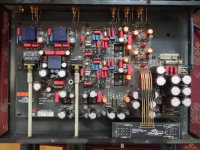
Some time ago I visited the Vinyl Engine website as I am a member there, they only have a user manual, unfortunately no schematic. This is where I got the idea that it was fed 30vac well that and the 4 diodes that sit alongside the incoming power which I took to be a rectifier. (see Pic. 1) after connecting 24vac to the brown and blue wires two of these diodes smoked (Pic.1 CR10,CR13)
The model I have is the phono drive deluxe which has an off board power supply three wires enter the chassis Blue, Green Brown.
(Pic.3) carrying either DC or AC.
I presumed the rectification was going on onboard considering the banks of capacitors
I hope this further information and the photo's can help solve the problem. I would hate to see the unit end up in landfill as it was a very nice sounding devise.
Kind Regards Robert
According to the document that PRR attached eariler its 30VAC - 0 - 30VAC, but more importantly Pin 1 is 0V. If that Pin 1 matches up to pin 1 inside of the pre also then that would be a problem. So if you connected your VAC up to the brown and blue wires one of those was supposed to be the center tap. You really need to pull the board and inspect the backside of the board and visually identify which pin is the center tap. Take pictures and post them if you are uncertain. You'll have to pull the board to replace the burnt rectifiers anyway.
Thanks Chamberman for your help. Well I eventually pulled the board and desoldered the two diodes circled in fig.1. I have also marked up where the blue green and brown wires enter the board but am no better off as regards where the 0 volts centre tap goes and +- 30v.
I can't see any traces leading from either the blue or green solder pads. Any thoughts guys.
Thanks Robert
I can't see any traces leading from either the blue or green solder pads. Any thoughts guys.
Thanks Robert
- Home
- Source & Line
- Analogue Source
- Mod Squad power supply voltages