HAPPY NEW YEAR fellow builders!
Quite a few threads on DIYAudio have discussed this amplifier designed by Rod Elliott (Project 101 at sound-au.com). Yet, I have not seen much of any performance measurements of finished implementations. It occurred to me that I could share some of mine after having experimented with feedback compensation in my build. After all, I have to give credit to great minds here who showed and explained their designs.
A disclaimer is due before I move on: my daily job has nothing to do with EE, I am just a curious constructor, and this is my first class-AB amp. So, I make no pretense of TRULY knowing what I am doing.
. . .
While waiting for the PCBs from ESP I spent a good while at a simulator. The simulator did provide for a very stable amp with complex loads however THD at higher frequencies gave me some hesitation. While THD-1kHz was below 0.01% on simulator within the whole power range, the THD-20kHz was rising quickly with output to well over 0.5% way before clipping. The 10 kHz square wave output looked too "triangular" on simulator, and I had noticed the same shape in a scoped output waveform of a real build by a member here. The slew rate on simulator was barely reaching 5V/us. Theoretically, this should be good enough for my low power implementation (25W into 8R, both channels driven). But wait, Rod had mentioned in his description that SR is 15 V/us and that it can easily be increased... I got curious.
It might have been a neophyte's blunder with the sim, but where? There are too few components in the design that could be considered suspect of performance limitation. I began tinkering with feedback compensation and will try to show what I did whilst keeping compliant with Rod's explicit rule not to disclose circuit component values not revealed in the public page of the project. If you have the boards purchased from ESP then you have access to complete information.
Plain reduction of the Miller cap C3 around VAS Q7 in P101 default version (see my circuit fragment doodles below) predictably led to improved THD but also deteriorated stability - a scary area for me where I did not want much compromises. How do I reduce the C3 and yet maintain acceptable stability margins? Long story short, I ended up building first a modification which I denote as "Version A", measured it, then tinkered on and finished up with "Version B". Both turned out to be working well, reducing THD notably compared to the simulated default arrangement. Version B, as far as I understand, can be considered as a variation of TMC. Please correct me if I am wrong. I derived it from the multiple elaborate compensation ideas used in other amps and discussed in SS threads. A definitive overkill for this amp but a good cure for curiosity. I had also trimmed some component values and set LTP tail current in Version A at ~1.7mA, and in Version B at ~2.8mA. It was an important step but had much less impact on THD improvement compared to the compensation circuitry. Everything is inter-related, though.
Picture below shows the three compensation schemes and corresponding loop gain graphs with stability margins (simulated) - the Project default, the Version A and the Version B:

Here is the scoped square wave response for versions A and B with 8R resistive load and with 100nF in parallel with 8R. In neither case an output inductor was used. Visually, the difference between the versions is insignificant and the ringing in case of 100nF||8R load is in my opinion acceptably contained in both versions. In my final build I did include small output L||R cells just to play it safe.

In absence of sufficiently fast square wave generator I could not reliably measure SR, but the ones predicted by the simulator were 32V/us for ver.A and 28V/us for ver.B.
Next comes comparison of THD measurements I took at different frequencies and output levels:

While there is little difference in THD at 1kHz between A and B (could be within measurement error), higher frequencies do reveal discernible advantages of version B at powers above a couple of watts. Interestingly, THD value of ver.B has some minimum at about 5W output while ver.A has it at around 1W. I have not figured out yet the mechanisms behind this behavior. As well, my measurement rig is quite simple and I am learning yet, so results may not be reliable in absolute terms but were good enough to spot the differences and ballpark the achievable THD levels. THD of ver.B at frequencies above 5kHz is probably somewhat lower as the shown results are bordering with soundcard's capabilities.
When it comes to distortion spectrum components, it looks like ver.B does a better job in suppressing higher order ones starting from the 5th at higher frequencies. The 1 kHz is peculiar though (with suppressed 2nd and 4th as well), but THD is overall low so I did not concern to investigate. The green dotted line in the plots below is added at -100dBc for easier comparison. Also note how the noise shaping of my sound card alters the graph when run at sample rates of 96kHz and 192kHz for measurement above 5kHz. As well, you can see the very unfortunate pick-up of SMPS radiation just below 80kHz due to its proximity to the measured channel in my (too) small enclosure. The other channel suffers from this garbage much less due to being located some ~30mm further away from the culprit than the shown channel... One of my real blunders (aka lessons).

Two tone IMD (19+20 kHZ) also confirmed notable improvement (about twice lower) in ver.B compared to ver.A. Here is ver.B measurement at 25W output:

. . .
So, did I find the answer to the catch of SR differences between those stated by the designer and those I saw in the simulator? Most probably not. Rod must have done something different/clever. But I have now learned about the effects the compensation makes on loop gain even in a rather simple amplifier topology and hence on THD performance. I cannot report to you whether the amp now sounds any better unfortunately. I just took the liberty of getting sidetracked by a peculiarity noticed in the project description vs. my simulation. If not for that, I would have just soldered up the thing and enjoyed it anyway.
In conclusion I would like to stress that I did not intend this thread to be about "how to improve P101". It is what it is and does not need improvements. I have not seen a single complaint from builders about its sound quality or reliability issues. Its ratio of user satisfaction to complexity appears to be very high in the environment of other much more sophisticated designs available for DIY. I am glad it turned out into a great learning curve for me without smoking anything. I mean components. Thanks for having a look and commenting.
Quite a few threads on DIYAudio have discussed this amplifier designed by Rod Elliott (Project 101 at sound-au.com). Yet, I have not seen much of any performance measurements of finished implementations. It occurred to me that I could share some of mine after having experimented with feedback compensation in my build. After all, I have to give credit to great minds here who showed and explained their designs.
A disclaimer is due before I move on: my daily job has nothing to do with EE, I am just a curious constructor, and this is my first class-AB amp. So, I make no pretense of TRULY knowing what I am doing.
. . .
While waiting for the PCBs from ESP I spent a good while at a simulator. The simulator did provide for a very stable amp with complex loads however THD at higher frequencies gave me some hesitation. While THD-1kHz was below 0.01% on simulator within the whole power range, the THD-20kHz was rising quickly with output to well over 0.5% way before clipping. The 10 kHz square wave output looked too "triangular" on simulator, and I had noticed the same shape in a scoped output waveform of a real build by a member here. The slew rate on simulator was barely reaching 5V/us. Theoretically, this should be good enough for my low power implementation (25W into 8R, both channels driven). But wait, Rod had mentioned in his description that SR is 15 V/us and that it can easily be increased... I got curious.
It might have been a neophyte's blunder with the sim, but where? There are too few components in the design that could be considered suspect of performance limitation. I began tinkering with feedback compensation and will try to show what I did whilst keeping compliant with Rod's explicit rule not to disclose circuit component values not revealed in the public page of the project. If you have the boards purchased from ESP then you have access to complete information.
Plain reduction of the Miller cap C3 around VAS Q7 in P101 default version (see my circuit fragment doodles below) predictably led to improved THD but also deteriorated stability - a scary area for me where I did not want much compromises. How do I reduce the C3 and yet maintain acceptable stability margins? Long story short, I ended up building first a modification which I denote as "Version A", measured it, then tinkered on and finished up with "Version B". Both turned out to be working well, reducing THD notably compared to the simulated default arrangement. Version B, as far as I understand, can be considered as a variation of TMC. Please correct me if I am wrong. I derived it from the multiple elaborate compensation ideas used in other amps and discussed in SS threads. A definitive overkill for this amp but a good cure for curiosity. I had also trimmed some component values and set LTP tail current in Version A at ~1.7mA, and in Version B at ~2.8mA. It was an important step but had much less impact on THD improvement compared to the compensation circuitry. Everything is inter-related, though.
Picture below shows the three compensation schemes and corresponding loop gain graphs with stability margins (simulated) - the Project default, the Version A and the Version B:
Here is the scoped square wave response for versions A and B with 8R resistive load and with 100nF in parallel with 8R. In neither case an output inductor was used. Visually, the difference between the versions is insignificant and the ringing in case of 100nF||8R load is in my opinion acceptably contained in both versions. In my final build I did include small output L||R cells just to play it safe.
In absence of sufficiently fast square wave generator I could not reliably measure SR, but the ones predicted by the simulator were 32V/us for ver.A and 28V/us for ver.B.
Next comes comparison of THD measurements I took at different frequencies and output levels:
While there is little difference in THD at 1kHz between A and B (could be within measurement error), higher frequencies do reveal discernible advantages of version B at powers above a couple of watts. Interestingly, THD value of ver.B has some minimum at about 5W output while ver.A has it at around 1W. I have not figured out yet the mechanisms behind this behavior. As well, my measurement rig is quite simple and I am learning yet, so results may not be reliable in absolute terms but were good enough to spot the differences and ballpark the achievable THD levels. THD of ver.B at frequencies above 5kHz is probably somewhat lower as the shown results are bordering with soundcard's capabilities.
When it comes to distortion spectrum components, it looks like ver.B does a better job in suppressing higher order ones starting from the 5th at higher frequencies. The 1 kHz is peculiar though (with suppressed 2nd and 4th as well), but THD is overall low so I did not concern to investigate. The green dotted line in the plots below is added at -100dBc for easier comparison. Also note how the noise shaping of my sound card alters the graph when run at sample rates of 96kHz and 192kHz for measurement above 5kHz. As well, you can see the very unfortunate pick-up of SMPS radiation just below 80kHz due to its proximity to the measured channel in my (too) small enclosure. The other channel suffers from this garbage much less due to being located some ~30mm further away from the culprit than the shown channel... One of my real blunders (aka lessons).
Two tone IMD (19+20 kHZ) also confirmed notable improvement (about twice lower) in ver.B compared to ver.A. Here is ver.B measurement at 25W output:
. . .
So, did I find the answer to the catch of SR differences between those stated by the designer and those I saw in the simulator? Most probably not. Rod must have done something different/clever. But I have now learned about the effects the compensation makes on loop gain even in a rather simple amplifier topology and hence on THD performance. I cannot report to you whether the amp now sounds any better unfortunately. I just took the liberty of getting sidetracked by a peculiarity noticed in the project description vs. my simulation. If not for that, I would have just soldered up the thing and enjoyed it anyway.
In conclusion I would like to stress that I did not intend this thread to be about "how to improve P101". It is what it is and does not need improvements. I have not seen a single complaint from builders about its sound quality or reliability issues. Its ratio of user satisfaction to complexity appears to be very high in the environment of other much more sophisticated designs available for DIY. I am glad it turned out into a great learning curve for me without smoking anything. I mean components. Thanks for having a look and commenting.


i would say that the "ringing" is in fact instablilty. (note that it occurs only on the negetive cycles), thus the compensation is suspect.Here is the scoped square wave response for versions A and B with 8R resistive load and with 100nF in parallel with 8R. In neither case an output inductor was used. Visually, the difference between the versions is insignificant and the ringing in case of 100nF||8R load is in my opinion acceptably contained in both versions. In my final build I did include small output L||R cells just to play it safe.
not a p101, but a useful guide (see post 2)Yet, I have not seen much of any performance measurements of finished implementations.
p.s. some time ago i asked a p101 builder whats the clipping like at 10KHz , but i did not get a response, how yours?
Last edited:
Sure, I agree, not perfect. Even though the amp recovers quickly from the ringing I installed output inductors in the final build. That choked the ringing of course.i would say that the "ringing" is in fact instablilty. (note that it occurs only on the negetive cycles), thus the compensation is suspect.
I am curious what kind of capactive load a regular loudspeaker presents to the amplifier? I mean not the electrostatic speakers. I measured my loudspeaker cable (5m) capacitance separately and it was ~1nF. I have not found yet a good answer on what capacitance is added by the speaker. When I should be concerned seeing ringing in a test.
Thanks for the link, very informative.not a p101, but a useful guide (see post 2)
p.s. some time ago i asked a p101 builder whats the clipping like at 10KHz , but i did not get a response, how yours?
I have not stressed my amp yet into clipping. I will set up for measurement and will come back. Just give me a few days.
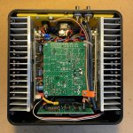
Hi Jacques,Nice chassis Nonills: where from ?
the chassis is from a mini-ITX PC series except the top lid which was made on order. The chassis measures 20cm x20cm x8cm. I got mine from here:
https://www.teknistore.com/en/mini-...8305809.html#/5375-colorsize-black_empty_case
I wanted it to match my preamp that I build before the amp (seen below the amp on the picture) and which uses the same type of mini-ITX box just 6.5cm in height.
you maybe aware already when testing at 10KHz, with the typical zobel of 100n+10R, the resistor will get hot.I have not stressed my amp yet into clipping
run it w/o the zobel, hopefully it remains stable.
for version B, note the phase margin is small between 40K-300K, it would not take much to go into osc there.
<<..with the typical zobel of 100n+10R, the resistor will get hot>>for version B, note the phase margin is small between 40K-300K, it would not take much to go into osc there.
Thanks for reminding about the zobel heating up. Forgot it. I will have to be very brief with this test as I would really not like to take the amp apart yet again to disconnect the zobel. Hope it survives.
With regard to the small phase margin in the freq. section 40-300K, yes I am aware of that, it falls to 25 deg in the lowest point. Normally a no go. Yet, I had noticed very similar shape of LG plots in other designs with TMC/TPC type of compensation presented in DIYA with phase margin as low as 30 deg or even lower. And no one seemed to raise the stability concerns. I even saw someone mentioning that the phase curve can even cross the 180deg line as long as it returns back to above before the gain reaches unity. That did not make sense to me but who am I to tell. Maybe I misunderstood the context.
An interesting topic for me, thanks for addressing it and maybe you can direct me where this specific shape of LG plot wrt interim drop of phase margin has been discussed.
Project 101 at sound-au.com uses no drivers, the lack of which I know Bob Cordel is very clear about. And it explains the limited slew rate and possibly disappointing THD at high frequencies. MOSFETs have a large gate capacitance which requires more current to charge/discharge than is reasonable in the VAS of a high-power amplifier. And while using a boot-strap pull-up (down) is often a good idea, it may contribute to the slew and THD issues. The features of Douglas Self's "blameless" amplifier would improve this amplifier, including LTP degeneration and a Darlington VAS. Drivers would lower the impedance driving the FETs, moving those poles much higher and make a faster, more stable amplifier. Of course, this would make it more complicated, but if you are going to spend the money for the power supply, heat sinks and lateral FETs, a dollar or two more is well invested. I am not a fan of many overly complicated amps seen in DIYA, but Project 101 is a bit too simple and dated.
jacques, interesting design, what is the bias current on the complementary VAS? I mean the final one that drives the mosfets.
@Alexandre
For the AEM6000, bias currents are as follows:
Stage 1: 0.8mA per JFET (1.6mA total)
Stage 2: 1.2mA per side (2.4mA total)
Stage 3: 10mA
Output MOSFETs: 50mA
For the AEM6000, bias currents are as follows:
Stage 1: 0.8mA per JFET (1.6mA total)
Stage 2: 1.2mA per side (2.4mA total)
Stage 3: 10mA
Output MOSFETs: 50mA
With regard to the small phase margin in the freq. section 40-300K........................
direct me where this specific shape of LG plot wrt interim drop of phase margin has been discussed.
Attachments
Hi Alex,nonills, do you mind if I ask, which models did you use for the lateral mosfets?
thanks,
alex
I used the models included with the Microcap package. My experiences:
a) Exicons were right on mark for DC operating point/bias but were too "optimistic" for AC - ringing on square waves with capacitor added to the load resistor in reality begun at smaller capacitor values than in the sim;
b) Renesas were closer to reality in AC (but still optimistic) while DC was wrong - the devices were conducting with zero bias applied like depletion mode fets. I am using exicons in my build.
I concur very much with your view on complexity which is sometimes hard to justify. I also have seen the criticism of P101 just as you described and some more like unequal loading of LTP collectors which I presume is more pronounced with my version B compared to A even though producing less distortion overall. I chose Rod's project because I learned so much from his web site, I wanted to support his educational work by buying his boards and wanted something simple for my first AB amp. I am now certainly much better prepared to look into a design with, should I call it, "balanced" complexity. Crawl - walk - run sort of path. Choices, choices...Project 101 at sound-au.com uses no drivers, the lack of which I know Bob Cordel is very clear about. And it explains the limited slew rate and possibly disappointing THD at high frequencies. MOSFETs have a large gate capacitance which requires more current to charge/discharge than is reasonable in the VAS of a high-power amplifier. And while using a boot-strap pull-up (down) is often a good idea, it may contribute to the slew and THD issues. The features of Douglas Self's "blameless" amplifier would improve this amplifier, including LTP degeneration and a Darlington VAS. Drivers would lower the impedance driving the FETs, moving those poles much higher and make a faster, more stable amplifier. Of course, this would make it more complicated, but if you are going to spend the money for the power supply, heat sinks and lateral FETs, a dollar or two more is well invested. I am not a fan of many overly complicated amps seen in DIYA, but Project 101 is a bit too simple and dated.
I like Suzy J's projects. This one is among candidates on my list too.For lateral mosfet output, I largely prefer the AEM6000 over the P101, having built both.
- Home
- Amplifiers
- Solid State
- Compensation in ESP P101