Seems like my PQ10's power supply is broken. Positive rail is moving around 12v and the negative at around -2.5v.
I've never had a need to understand how a car amplifier's PS works, so I took the opportunity to do some reading. Pretty fascinating.
Nothing looks burned out. Nothing looks abused.
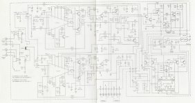
I really don't understand the circuit to turn Q801-4 on and off. I don't understand why the circuit on Q801/2 Base is so much different than Q803/4, I thought they'd be the same. (Schematic attached.)
Here are some measurements using 12.1vdc power to the amp:
Q801-4 (all four measure the same)
B=13.1v (erratic) And wouldn't C806 block the dc to the base on Q803 and 4?
C=0v
E=12.1v
Each Base measures around 30 hertz (erratic). I thought this would be well out of the audible range, like 50-100 kHz.
I don't measure any AC on the rectifier diodes (CR807 and CR808). I get -2.7vdc (erratic) out of CR807, and 12vdc (erratic) out of CR808. I also get 2.4vdc to ground on each rectifier on what I expect is the AC connections from the transformer.
I'll check around for a local repair shop, but thought I'd throw it out here first.
BTW, all measurements with a multimeter, no oscilloscope.
Thanks,
Dan

I've never had a need to understand how a car amplifier's PS works, so I took the opportunity to do some reading. Pretty fascinating.
Nothing looks burned out. Nothing looks abused.
I really don't understand the circuit to turn Q801-4 on and off. I don't understand why the circuit on Q801/2 Base is so much different than Q803/4, I thought they'd be the same. (Schematic attached.)
Here are some measurements using 12.1vdc power to the amp:
Q801-4 (all four measure the same)
B=13.1v (erratic) And wouldn't C806 block the dc to the base on Q803 and 4?
C=0v
E=12.1v
Each Base measures around 30 hertz (erratic). I thought this would be well out of the audible range, like 50-100 kHz.
I don't measure any AC on the rectifier diodes (CR807 and CR808). I get -2.7vdc (erratic) out of CR807, and 12vdc (erratic) out of CR808. I also get 2.4vdc to ground on each rectifier on what I expect is the AC connections from the transformer.
I'll check around for a local repair shop, but thought I'd throw it out here first.
BTW, all measurements with a multimeter, no oscilloscope.
Thanks,
Dan
Attachments
What is the DC voltage on all terminals of IC602?
Copy and paste the following list and fill in the blanks. If there is no blank space after the colon, add one between the colon and the numbers you enter. It makes it much easier to read.
Pin 1:
Pin 2:
Pin 3:
Pin 4:
Pin 5:
Pin 6:
Pin 7:
Pin 8:
Copy and paste the following list and fill in the blanks. If there is no blank space after the colon, add one between the colon and the numbers you enter. It makes it much easier to read.
Pin 1:
Pin 2:
Pin 3:
Pin 4:
Pin 5:
Pin 6:
Pin 7:
Pin 8:

I don't think this is going to be good news. Multimeter set to 20v range and Ground In as reference,What is the DC voltage on all terminals of IC602?
Copy and paste the following list and fill in the blanks. If there is no blank space after the colon, add one between the colon and the numbers you enter. It makes it much easier to read.
Pin 1:
Pin 2:
Pin 3:
Pin 4:
Pin 5:
Pin 6:
Pin 7:
Pin 8:
Pin 1: varies around 0.8v - 3.85v, seems to mostly read 2.35v
Pin 2: varies around 0.8v - 3.85v, seems to mostly read 2.35v
Pin 3: varies around 0.8v - 3.85v, seems to mostly read 2.35v
Pin 4: varies around 0.8v - 3.85v, seems to mostly read 2.35v
Pin 5: varies around 0.8v - 3.85v, seems to mostly read 2.35v
Pin 6: varies around 9v - 13v
Pin 7: varies around 0.8v - 3.85v, seems to mostly read 2.35v
Pin 8: varies around 3v - 7v
The pins with "varies around 0.8v - 3.85v, seems to mostly read 2.35v" read exactly like the outer pins of CR807 and CR808.
You have to use the secondary ground. The secondary ground is the triangle ground symbol. Any of the non-bridging speaker terminals will be the secondary ground. Pins 2 and 3 should be directly connected to the secondary ground, according to the diagram.
Well, that makes a difference, thanks!You have to use the secondary ground. The secondary ground is the triangle ground symbol. Any of the non-bridging speaker terminals will be the secondary ground. Pins 2 and 3 should be directly connected to the secondary ground, according to the diagram.
Pin 1: -0.045v
Pin 2: 0v
Pin 3: 0v
Pin 4: 0v
Pin 5: 0v
Pin 6: varies from 9.5v to 10.8v
Pin 7: 0.038
Pin 8: varies from 3.16v to 3.25v
And thanks for the link!You have to use the secondary ground. The secondary ground is the triangle ground symbol. Any of the non-bridging speaker terminals will be the secondary ground. Pins 2 and 3 should be directly connected to the secondary ground, according to the diagram.
If you place your meter across each individual channel and apply remote, do you see any DC readings on any channel?
Yes. Getting 6 to 9v dc on channel 3.If you place your meter across each individual channel and apply remote, do you see any DC readings on
I think this one is a bit beyond my skill/knowledge level.Did you check the output transistors in that channel (or any channel)?
I can see discoloration on the third transistor from the left. That is channel 3 with the dc on the output. And on the rail with the low negative voltage.You're here for help, not because you know everything. Post whatever questions you have if you decide to continue.
The washer is loose, but the screw is on tight. Maybe bottomed out?
I had the board out and maybe I didn't get that one tied down tight enough and it got hot?
If blown, could it shut down the amp?
When it went, the amp shut down, then came on and shut down a couple times. On my second trip in the car, so not right away.
And there is no continuity across any output transistor or power supply transistor across B, C, or E.
Check the output transistors. Meter on ohms. You should not read anything near 0 ohms between any of the legs of any individual transistor.
Re-reading a previous post... OL on all leg combinations on ohms seems virtually impossible. What does your meter read, on ohms, if you hold the tips of the probes together?
When set on 200 ohms and leads held together I get 0.1 ohms. When the leads are not toughing, I get OL.Re-reading a previous post... OL on all leg combinations on ohms seems virtually impossible. What does your meter read, on ohms, if you hold the tips of the probes together?
But when I measure between the legs, it will initially reads 60-90 ohms, then resets to OL. That is why I said there was no continuity.
Why do you think it has failed?
It's possible but when a transistor fails, it commonly fails with legs 2 and 3 shorted.
Set the meter to a higher range and compare the readings from the Ch3 output transistors to the corresponding output transistors from a different channel.
It's possible but when a transistor fails, it commonly fails with legs 2 and 3 shorted.
Set the meter to a higher range and compare the readings from the Ch3 output transistors to the corresponding output transistors from a different channel.
- Home
- General Interest
- Car Audio
- ADS PQ10 Power Supply Problems