A tiny power follower?
My curiosity was awakened by some posts in the JLH 10Watt class A amplifier thread. Member cumbb had posted a few photos of modest point to point creations declared to allow for a pleasant listening experience.
Other members appeared to be curious as well, but despite requests, a detailed circuit does not yet appear to have been revealed.
For the educated it is likely no challenge to figure out the circuit. But for myself without anything other than very basic knowledge in electronics, it will serve as a healthy brain exercise to figure out the circuit based on info from photos and enigmatic posts.
I started this thread to avoid filling the JLH-thread with off topic material while trying to figure out a working circuit.
=> Mr cumbb, if you in any way dislike or oppose to this thread or posting the circuits, please let me know and I will ask the Moderators to remove this thread immediately!
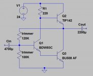
Post #4069 in the JLH-thread Mr cumbb post one of the first photos:

From this photo and from other photos in posts #4120 #4388 #4421 #4560, I am trying to dumb-luck myself to figure out a working schematic. The iterations evolve throughout the JLH-thread and post #4560 shows a called balanced version which would be the final objective to figure out.
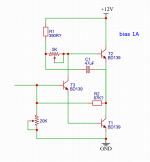
Starting with the initial creations from the first photos, I have so far tried with the circuit below. Even being significantly uncertain of component values it is actually producing music on a test speaker. Was not able to bias up to suggested 1A with 12V so will try to experiment further prior to testing on a better speaker.

Appreciate anybody's constructive suggestions and I really hope the creator himself, Mr cumbb will assist in resolving this matter.
Let's see how it might develop.🙂
❤️Disclaimer: This thread is started is started in a positive spirit only. If the content would awaken any primitive impulses or negative emotions within you: Please swiftly press the "go back" button in your device and you will moved away from whatever that aggravates your lesser evolutionary functions.❤️
My curiosity was awakened by some posts in the JLH 10Watt class A amplifier thread. Member cumbb had posted a few photos of modest point to point creations declared to allow for a pleasant listening experience.
Other members appeared to be curious as well, but despite requests, a detailed circuit does not yet appear to have been revealed.
For the educated it is likely no challenge to figure out the circuit. But for myself without anything other than very basic knowledge in electronics, it will serve as a healthy brain exercise to figure out the circuit based on info from photos and enigmatic posts.
I started this thread to avoid filling the JLH-thread with off topic material while trying to figure out a working circuit.
=> Mr cumbb, if you in any way dislike or oppose to this thread or posting the circuits, please let me know and I will ask the Moderators to remove this thread immediately!
Post #4069 in the JLH-thread Mr cumbb post one of the first photos:
From this photo and from other photos in posts #4120 #4388 #4421 #4560, I am trying to dumb-luck myself to figure out a working schematic. The iterations evolve throughout the JLH-thread and post #4560 shows a called balanced version which would be the final objective to figure out.
Starting with the initial creations from the first photos, I have so far tried with the circuit below. Even being significantly uncertain of component values it is actually producing music on a test speaker. Was not able to bias up to suggested 1A with 12V so will try to experiment further prior to testing on a better speaker.
Appreciate anybody's constructive suggestions and I really hope the creator himself, Mr cumbb will assist in resolving this matter.
Let's see how it might develop.🙂
❤️Disclaimer: This thread is started is started in a positive spirit only. If the content would awaken any primitive impulses or negative emotions within you: Please swiftly press the "go back" button in your device and you will moved away from whatever that aggravates your lesser evolutionary functions.❤️
Attachments

It has certain resemblance with the White Cathode Follower, BJT version. Where is the load connected and how? My logic says with a large capacitor from middle point to grround 🤔
This is how I have used the circuit so far, however I believe that cumbb recommended to input on T2, I have not tried it yet. Have not reached 1 amp bias, only abt 0.7AIt has certain resemblance with the White Cathode Follower, BJT version. Where is the load connected and how? My logic says with a large capacitor from middle point to grround 🤔
I dislike the wiring of T3. There is some AC current flowing through its collector to T2 base. There is also anothe current flowing in C1 (seems to be a bootstrap). As they are different in magnitude, they mar recirculate between them counteracting in place of helping them.
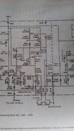
I saw this schematic close to an old vertical deflection circuit in Philips TV set.
I saw this schematic close to an old vertical deflection circuit in Philips TV set.
Attachments
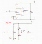
Observe the driver is wired to the middle point directly acting as DC NFB.
(The last pic is involuntarily rotated)
(The last pic is involuntarily rotated)
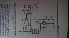
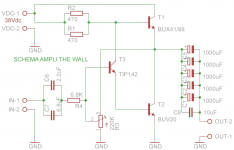
May be, the BD139 are too weak to reach 12 V and 1A.
I did use BD441 or TE13003 or BD180 or others; had reached 36 V > 1 A.
R2 as trimmer.
Later remove C1.
Use this circuit - including R2 from above:
I did use BD441 or TE13003 or BD180 or others; had reached 36 V > 1 A.
R2 as trimmer.
Later remove C1.
Use this circuit - including R2 from above:
Attachments
Last edited:
https://www.tforumhifi.com/t40025-the-wall-class-a-commenti-al-progettoSimilar schemes were built in the 2010s at the Italian forum.
My suggestion:
Whoever has a JLH could gradually rebuild, inclusive of the listening experiences to be made, change experiences. For example, you could start by extracting the input transistor. But then make sure that you connect the speakers with the polarity reversed. BUT: With speakers with passive crossover components, the sound could then suffer greatly. So start with the loudspeakers: Use speakers without crossovers: E.g. very good, sophisticated full range;-)
Whoever has a JLH could gradually rebuild, inclusive of the listening experiences to be made, change experiences. For example, you could start by extracting the input transistor. But then make sure that you connect the speakers with the polarity reversed. BUT: With speakers with passive crossover components, the sound could then suffer greatly. So start with the loudspeakers: Use speakers without crossovers: E.g. very good, sophisticated full range;-)
Thank you everyone for contributions! Listening now to one channel on my better speakers.
Its peculiar, Three BD139, a few trimmers, resistors and input and output cap put together without electronics knowledge and it sounds completely clean and detailed.😀
Next I have to put together a better PSU so that I can feed the next channel.
Naturally output power is modest and I suppose it is clipping that I hear when I crank it up but still I am surprise over the result.
Possibly this THD-thingy is not all that important after all😕
Mr. Cumbb, could you suggest some suitable fullrange drivers?My suggestion:
Whoever has a JLH could gradually rebuild, inclusive of the listening experiences to be made, change experiences. For example, you could start by extracting the input transistor. But then make sure that you connect the speakers with the polarity reversed. BUT: With speakers with passive crossover components, the sound could then suffer greatly. So start with the loudspeakers: Use speakers without crossovers: E.g. very good, sophisticated full range;-)
There is a long list of fullrangespeakers. But in german: Click on the homepage at the bottom: "Produkte" (products) and then on "Breitbandlautsprecher" (broadbandloudspeakers;-)
Problem now: I would get me any driver to run, to a good sound. I can not give great recommendations, because also room decor, room size, listening habits, expertise in installation and placement and so on would have to include. But a choice based on diaphragm area, diaphragm material and efficiency and costs is feasible here.
Hands off "phase plug" drivers!!!
http://www.spectrumaudio.de/
Two more essential tips to help cone speakers, even full-range speakers, sound good.
For fullrange never use a passive crossover or any electrical components.
The driver must be braced, clamped. The point is that a) the magnet and the basket do not swing around and b) the driving force is countered by a maximum counterforce. A simple wooden strip and a screw will do.
The diaphragm must be coated with a strong damping "glue" - silicone adhesives for bathroom installations or "modern" adhesives that acquire a rubber-like consistency after drying.
The point is a) horizontal constriction, which becomes more important with increasing frequency, and b) damping of the outer membrane surfaces - as well as an increase in mass, since by fixing the chassis we reduce the fundamental and low frequency resonances. Simply, according to the sketch 1, a thin coating, and if that is not enough, a wider thin coating (sketch 2). And if that is still not enough, then another even wider thin coating (3). And if you still miss the bass, then coat the back. Start in the same way as sketch 1.
A mechanical sound tuning that also eliminates errors of drivers that an electronic one cannot.
Attachments
![DSCN0209[1].JPG](/community/data/attachments/1034/1034508-5724e5d4e6146643446434685c6dc8b8.jpg?hash=VyTl1OYUZk)
;-)
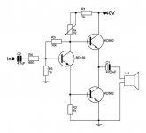
Genesis;-)
Because the JLH is a wonderful base to learn a whole lot and to get to your LAST, because a best sounding (with a highest sonic potential) amplifier/follower: probably the first and simplest circuits in electrical education;-)
Also ideal to get to know the sonic difference amplifier and follower.
The resistors circled in orange could be omitted. Step by step;-)
Do not use wire resistors.
Uses only two legs of the trimmers.
Positive feedback in followers or current source is feasible (orange sun). Also works sonically comparable Darlingtons.
The quality of the components is now crucial;-!!!!!
Have fun;-)
Attachments
![DSCN0214[1].JPG](/community/data/attachments/1038/1038618-4137aa1d7e09bb073641f8c363ed8096.jpg?hash=QTeqHX4Juw)
Because also concerning current, circuit very much lies in the arrears: some small thinking tasks;-)
By the way: I don't know of any capacitors, tubes, power transistors, where the circuit, current has been considered. And also most resistors show a careless construction. All complex circuit board layouts are fundamentally a mess.
All this nonsense is in the way of a good, clean sound, in the way of "HighEnd"-)
Attachments
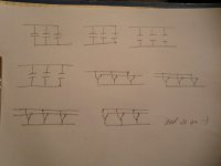
I will use this thread to point out some unexamined theses in the audio electronics discourse.
PSU: On a "complementary voltage power supply" for common complementary transistor PP amplifiers.
1: The usual power supply circuit. The usual belief to achieve maximum charge and "smoothing". You can see it with sight-measurement;-)
2: The already much better sounding variant. Half charge, less smoothing. But it sounds much cleaner, finer and also more fine-dynamic. How so;-?!
3: Even cleaner and finer than 2. What;-?!
4: A nevertheless further step: Try it with only ONE voltage. Look for appropriate amplifiers;-)
But: Why does it sound cleaner, more precise, finer, higher resolving and also more dynamic in this order step by step;-?! What must we obviously overlook - or overhear;-?
Attachments
![DSCN0249[1].JPG](/community/data/attachments/1056/1056527-cb7dfae9db68cd45d43db034fe553868.jpg?hash=y3366dtozU)
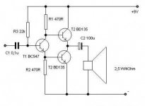
Have you tried different types of diodes? What would be better, faster or slower?I will use this thread to point out some unexamined theses in the audio electronics discourse.
PSU: On a "complementary voltage power supply" for common complementary transistor PP amplifiers.
The underestimated RCA scheme (1966). It can be assembled from various available parts for different power 1-50W.A nevertheless further step: Try it with only ONE voltage. Look for appropriate amplifiers;-)
Last edited:
- Home
- Amplifiers
- Solid State
- Cumbbs Koans