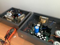
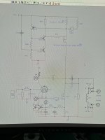
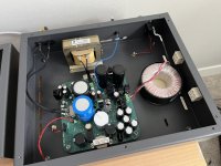
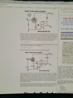
This design is taken from TubeCad. I ended up using a single Exicon TO-264 mated to a JJ 6922. The cathode / gate voltage’s matched up nicely. Regulated power supply for the Mosfet. Voltage Multiplier for the B+. High Freq Inductor from Hammond. I will post measurements in the near future. I am excited it didn’t explode upon power up. Current stabilizes ~ 7 seconds. 8 watts @ 8/4 ohms.
Dwight


Dwight

Their whole area is so clean! I don't see one spec of dust! Drink rings don't count 😛Clean looking build, very interesting.
I'm guessing the OP doesn't live within 500M of two large condo builds...
@happyrabbit Beautiful PCB design, too.
Gimp,Zoom,Koda -> Thank you !
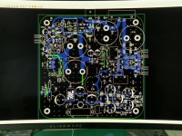
attached the pcb layout. 4 layers with the middle layers being the ground planes. Attempted to keep the high current loop as small as possible. the 2nd pic is my split load amp next to the super triode. I liked the split load amp but wanted a triode harmonic profile. ( Aka 2nd order )
Dwight
attached the pcb layout. 4 layers with the middle layers being the ground planes. Attempted to keep the high current loop as small as possible. the 2nd pic is my split load amp next to the super triode. I liked the split load amp but wanted a triode harmonic profile. ( Aka 2nd order )
Dwight
Attachments
Last edited:
A good looking build. I looks like the output FETs each dissipate about 19 watts, how do you deal with the heat?
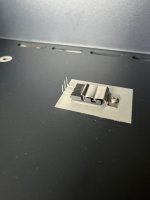
What is the value of the drain load inductor?
I think I have answered the second question using a magnifying glass 14mH @ 5A , 60Hz to 10kHz.
For those interested XL at 60Hz will be 5.3 ohms.
ken k
What is the value of the drain load inductor?
I think I have answered the second question using a magnifying glass 14mH @ 5A , 60Hz to 10kHz.
For those interested XL at 60Hz will be 5.3 ohms.
ken k
A good looking build. I looks like the output FETs each dissipate about 19 watts, how do you deal with the heat?
What is the value of the drain load inductor?
I think I have answered the second question using a magnifying glass 14mH @ 5A , 60Hz to 10kHz.
For those interested XL at 60Hz will be 5.3 ohms.
ken k
using a single to-264 exicon attached to a 3.3mm aluminum case. ~80c @ 36w.
here is the link for the inductor -
https://www.hammfg.com/files/parts/pdf/197J5.pdf
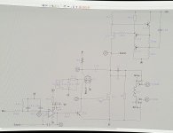
Also attached my schematic.
dwight
Member
Joined 2006
What is the "split load" version arrangement? I see two inductors, but P-P wouldn't need them at all.
https://www.diyaudio.com/community/threads/a-zen-split-load-amp.374496/What is the "split load" version arrangement? I see two inductors, but P-P wouldn't need them at all.
Thanks for the "split load" link. I can see where using two windings on the same core would be helpful for the split version. More inductance and lower output impedance.
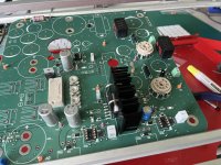
pic with Mosfet and bipolar npn with thermal pads.using a single to-264 exicon attached to a 3.3mm aluminum case. ~80c @ 36w.
here is the link for the inductor -
https://www.hammfg.com/files/parts/pdf/197J5.pdf
Also attached my schematic.
dwight
pic with Mosfet and bipolar npn with thermal pads.
Are you building 2 of these? Using 1/2 of the 6922.
Yes. Two mono blocks.Are you building 2 of these? Using 1/2 of the 6922.
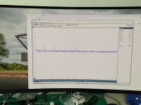
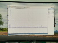
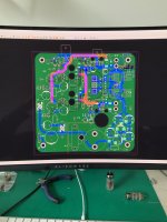
here is the FFT @ 2.5w @ 8r. I had to redesigned the pcb to use a single center tapped transformer. the dual transformer configuration had way too much 120hz noise. The single setup is better but the 120hz energy still haunts this concept. Changed the tube to the jj ecc99. I prefer the 6922 after listening awhile. 6922 has more meat on the bones. Based on the 120hz noise , I plan to replaced the load inductor with a Mosfet based CCS. See attached. the peaks beyond 11khz are from the differential probe / signal generator.
dwight
dwight
Attachments
Did you choose surface mount stuff for convenience or ? For DIY surace mount makes it more difficult for most of us.
Self taught. Over the years I have become more comfortable with SMD’s. Many of the DIP ic’s have disappeared with COVID. The smallest i will design with is 1206 & SOIC-8. I can remove them safely without destroying the pcb. SMD parts do allow for much tighter layouts. See attached. The 5x voltage multiplier in the low right corner is super compact Using SMD’s.
dwight

dwight
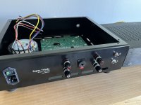
Switched directions.. 6922 connected to a TI OPA541. Same concept as the 6922 / Exicon. ~6 watts. Added a 1/4 headphone jack + khozmo attenuator. My 1st integrated amp. See attached.
Dwight
Dwight
Attachments

- Home
- Amplifiers
- Tubes / Valves
- Super Triode Single Ended Amp