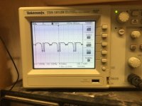
Supposed to be a fairly straightforward balanced to SE converter - “oscillating” with a very strange 120/60 Hz square-ish wave oscillation. Not like it’s just picking up hum, which would be a sine wave (Or at least half sines). I can inject a signal (sine wave or music) but it just rides on this “signal”. There are actually two traces, not quite overlapping which are the two channels at slightly different amplitudes, but the wave shapes are identical and defy explanation. Tubes are 6BQ7’s. Same ones work properly in the phase splitter of the power amp. Power supply is a mosfet regulator - gate voltage comes from a zener stack and filter cap, which feeds two mosfets. One for the power amp front end, the other is feeding this (the supply itself is clean). No clue as to what is going on.
Barring a resolution, next step would be to do away with the global feedback. But that would require degeneration of the LTP to get the gain down to 2X. I don’t have enough voltage overhead for the CCS to put in that big a cathode resistor in each half of the LTP. Last time I did that I had a -200V supply to work with.
Barring a resolution, next step would be to do away with the global feedback. But that would require degeneration of the LTP to get the gain down to 2X. I don’t have enough voltage overhead for the CCS to put in that big a cathode resistor in each half of the LTP. Last time I did that I had a -200V supply to work with.
Attachments

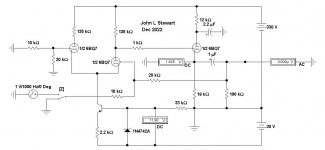
Do you have grid stoppers at the first tube grids? The anode resistors seem a bit high. Perhaps you can increase the idle current. Also place a filter capacitor right at the top of the anode resistors. Finally, a small amount of degeneration in the form of 100R cathode resistors couldn't harm.

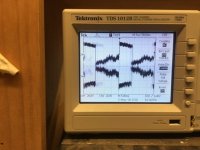
It’s definitely just being picked up somehow. Pulled the CF allowing it to run open loop, and I’m gettting that weird waveform at both plates. Higher amplitude too - looks like the feedback was trying it’s best to null it out.
Its also periodic in 60Hz so big clue there. Maybe heater cathode short. Check HT too. Or it is that your heaters are floating. Try two 100R in series in the heaters with the centre to ground.
Last edited:
I have the 100 ohm resistors on the heater winding. H-k issues is what it smells of, but the tubes were working properly in an LTP phase splitter on this same chassis. The power amp section is disconnected now as I work the preamp. Dedicated heater winding for the preamp section, too.
Maybe it is h-k leakage that didn’t show up before. I’ve had the strangest things happen - an LTP that latched to one side every other power up, but that was a 200 year old 12SN7. When I had the heaters floating once, I had complementary k-followers break into a 60 Hz square wave oscillation when the audio level going in got high enough (quiet till then, and self-quenching when the audio level reduces).
Ill give it a day or two before going back.
Attachments
Does the oscillation sync with the line frequency? Trigger the the scope on line and see if the waveform is phase locked.
The 2nd tube C floats at 75V. That may be too much for the H-C leakage.
Try to elevate the heater to about half way, say 35V. That should fix most of it.
Jan
Try to elevate the heater to about half way, say 35V. That should fix most of it.
Jan
I’m reading between 75 and 80 volts at the plates, with a pair of 270k in each location, which is why it settled at that value. I originally had lower value resistors but the plates were running too high, leading to excessive h-k in the follower. It wasn‘t making much sense to me either why R had to run that high to bring the plates down.
With that huge asymmetrical signal, the DC reading is probably incorrect. Got to get rid of that before trying to Re-center the Q point.
With that huge asymmetrical signal, the DC reading is probably incorrect. Got to get rid of that before trying to Re-center the Q point.
As I mentioned, the anode load resistors seem too high. I would use 68k there.
Another point worth mentioning: with direct coupled CF one has to insert a protection diode between cathode and g1 in reverse direction. It will protect the g1 going positive wrt the cathode at turning on.
Another point worth mentioning: with direct coupled CF one has to insert a protection diode between cathode and g1 in reverse direction. It will protect the g1 going positive wrt the cathode at turning on.
Better connect both inputs to common, removing the input signal.
See where the DC voltages are at zero signal. The drop across 135K with 2.5 mA is 343,75V.
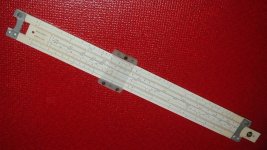
Don't need a Sim to solve this cct. All can be done with pencil, paper & slip stick. 🙂
👍
See where the DC voltages are at zero signal. The drop across 135K with 2.5 mA is 343,75V.
Don't need a Sim to solve this cct. All can be done with pencil, paper & slip stick. 🙂
👍


68K is a much better plate load. Now the cct actually makes sense. And it works! 🙂
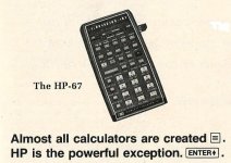
I've still got that slip stick. But these daze mostly using the HP67,👍
I've still got that slip stick. But these daze mostly using the HP67,👍
Attachments
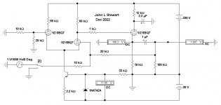
The problem is that both channels are somehow interfering with one another. 68k is a “better” value - to split the difference evenly between the tube and the resistor. But results in cathode voltage being a bit out of comfort zone on the follower. But I tried it and it worked in the one channel I modified. I left the other unpopulated. So I put the original 100k back in the other channel, and it worked too. Plate voltages sat at 85 volts which is what I wanted in the first place. Run both channels at the same time, and I get the screwed up 60 Hz waveform and the plate voltages rise (because of the waveform asymmetry, I presume). Either one by itself is fine. I guess I’ll be recomputing for a 270 volt B+, drop 50 in a resistor and RC filter the supplies for each diff pair individually. The two LTP splitters for the power amp were able to share the same supply, but I guess these just won’t.
paper & slip stick.
Clarification. That IS Rein Narma but not his slip-stick:
(cj hands Rein a slide rule)
"I haven't used one of these in ages."
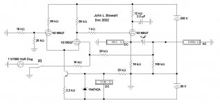
The drop across the 12K decoupling cap to a single CF is ~100V.The problem is that both channels are somehow interfering with one another. 68k
Each CF needs an independent decoupling network. Otherwise interference between channels is a sure thing.
When I first looked at that original schema I thought it was an error. It is, 😱
The channels were interfering with one another whether the followers were hooked up or not. Both LTPs simply would not run at the same time. So I individually decoupled them, and we were back to the same ********. With or without the followers. The only other possibility was the current sources. They are completely independent, or at least supposed to be. But that’s where the problem ended up being. Replaced them with tail resistors and both channels function properly. With the 5.6k the current is a bit off and it pulls the plates down to about 55V (vs 80 to 85) but there is still enough headroom for a signal.
Any ideas what the hell would cause two completely independent CCS’s to talk to one another like that? The ones on the phase splitters don’t do that - mounted on the same kind of terminal strip. They just go to ground instead of negative supply, since the cathodes sit at 80V instead of just above ground. I suppose I could voltage double the -30 volt supply and make a -30 for the output stage bias and -60 for the input LTPs to gain some CMRR and just bias the damn things with resistors.
Any ideas what the hell would cause two completely independent CCS’s to talk to one another like that? The ones on the phase splitters don’t do that - mounted on the same kind of terminal strip. They just go to ground instead of negative supply, since the cathodes sit at 80V instead of just above ground. I suppose I could voltage double the -30 volt supply and make a -30 for the output stage bias and -60 for the input LTPs to gain some CMRR and just bias the damn things with resistors.
Attachments

- Home
- Amplifiers
- Tubes / Valves
- Tube op-amp WTF