I have had this amp for about 10 years and haven't done much with it other than play with different tubes. I started looking around the web for info on it and found most pictures and reviews showed it having 6L6 outputs, but the 3 different schematics I found showed EL34. The other odd thing I noticed is that 2 schematics showed it connected as a pentode, the other shows connection to "ultra-linear" taps, but all still EL34s. Mine was connected as pentode with G2 connected to B+ thru a 10K resistor and G3 tied to cathode. I pulled the output xfmr caps off and found they actually have the UL taps, so I have connected wires to them and run them down into the bottom area. while I had it apart I decided to check the transformer impedance ratio, turns out it's 4.4K P-P and the taps are 43%, pretty much standard UL configuration. So now I wonder why they would have built it like this? The other odd thing is that they indicate the bias is different for each output tube, and they use different plate resistors in the driving 6SN7, I have no idea why it's built this way?
Anyway, the amp is well built and I am going to play with it in various configurations. First, start with figuring out which tubes to use, 6L6 or EL34.
Your thoughts?
Cheers

Anyway, the amp is well built and I am going to play with it in various configurations. First, start with figuring out which tubes to use, 6L6 or EL34.
Your thoughts?
Cheers

1. The 6L6, 6L6G, 6L6GA, and 6L6GB screens are only rated for 270V, 2.5 Watts.
A 10k screen resistor might have been there to alleviate the 430V B+ when they are in either pentode mode or ultra linear mode.
The 6L6GC screen is rated for 450V, 5 Watts, Big Difference!
The EL34 screen is rated for 450V, 8 Watts. A Very Big Difference!
A 220 Ohm screen resistor makes sense with 430V B+.
2. The 6N8 with 15k common cathodes resistor is a poor-man's Long Tailed Pair phase inverter, LTP, (not long tailed at all).
The 15k resistor is returned to ground, instead of a 150k resistor returned to a very large negative voltage (the latter is more long tailed).
The poor-man's long tail does not use / does not have a true current source; instead it uses a 15k resistor on the parallel cathodes.
Since g1 pin 1 gets the whole signal directly, and the g1 pin 4 is at AC signal ground, there would be more signal plate current at pin 2.
The cathode pin 3 couples signal current to Both cathode pin 6, And the 15k resistor to ground (cathode pin 6 and 15k share cathode pin 3's signal current).
That means less signal current to cathode pin 6, so less signal current to the plate pin 5.
With less signal current on plate pin 5, we need a 51k plate load; there is more signal current at plate pin2, so we only 47k plate load.
The larger signal current in 47k, versus the smaller signal current in 51k, gives about the same signal voltage out for both phases.
If you use a true CCS (constant signal current sink) instead of a 15k resistor, then the plate load resistors for pin 2 and pin 5 must be equal resistors
(Either both 47k, Or both 51k; use precision matched resistors).
Push Pull Output Transformers . . . Hate plate currents that are not equal. That is why they set the bias current on each output tube of a push pull pair, to make the output transformer happy (no early lamination saturation when the currents are balanced; versus early saturation if the currents are un-balanced).
Be sure to make the voltages across the 10 Ohm resistors equal, for equal cathode currents (near equal plate currents and near equal screen currents). Of course, those 10 Ohm resistors need to be precision matched.
The only other alternative is to use Exactly Matched output tubes for a push pull pair.
I am sorry for the complex answers.
Happy Experimenting!
Happy Listening!
Last edited:
Thank you so much for the detailed reply, I understand the "cheap" LTP now. I still don't understand why they would bias the output tubes differently though, wouldn't that create DC in the primary winding, something to avoid? And also crazy low bias values, 18mA and 9mA...I would think a happier spot would be around 30-35mA each tube?
Cheers
PS that schematic is not how my amp is wired, it's wired pentode with all G2 tied together going to that 10K B+ resistor. As I have it all apart I am adding the wires from G2 terminals on the xmfrs so I have an option to make it UL. But the P-P impedance is still 4.4K, and I can't seem to find any data for either tube that puts them in a happy spot. I am now looking for online LL calculators to play around with both tubes. Also, heater current 1.5A on EL34, only .9A on 6L6GC. Too bad Opera is not answering any of my emails, not sure if they still exist??
Last edited:
The Dyna Stereo 70 used EL34 outputs in UL, and had a 4.4k p-p primary.
I have no idea why your amplifier used such a large difference in cathode currents.
With only 9mA or 18mA, the output tubes would go out of 'class a' into 'class ab' portion at very low signal amplitudes.
And, that would not be a symmetrical class ab, since one tube cuts off very early, and the other tube cuts off less early.
Perhaps the bias pots were mis-adjusted, or the tubes became poorly matched, or lost their match as they became aged.
Last edited:
I wired up the UL connections and powered it up carefully and biased the 6L6GCs to 35mA and made a few tests. Everything worked great and it put out 26W just before clipping. Then I switched to 6CA7s and adjusted the bias to the same 35mA and made the same tests, this time 42W out. Tomorrow I will fire up the HP339A and see how the distortion measures with each set of tubes, then try the listening tests.
Thanks for the help.
Cheers
Thanks for the help.
Cheers
I'm finally back on this project and have been playing with it for a week, and doing a lot of research trying to nail down some of the anomalies in the diagram vs my amp.
First thing I found out is the cct brd in the amp could be either for the M99 or the M100 and it turns out mine is the M99 and uses a different tube line up. The other thing I found is this schematic originated from an Asian DIY site where someone reversed engineered the cct and came up with this when they were troubleshooting the amp which is why the bias voltages were wrong. Turns out all the documentation and reviews I could find for the amp indicates the tube lineup is 12AX7 into 6SN7 into 6L6GC. So I have updated the schematic for anyone else who finds this thread and can now continue tweaking it for better performance.
I setup the 339A and scope and have been playing around with EL34 and 6L6GCs in both UL and triode wired, interesting results as indicated below.
All @ 1KHz 8R and 16R, 2 measurements distortion at 1W and power at 1% distortion measured on the 8 Ohm output. ( there is only 4 and 8)
6L6GC U/L @ 45mA bias
8 Ohm
1W = .25%
13W = 1%
16 Ohm
1W =.135%
30W =1%
6L6GC Triode @ 48mA bias
8 Ohm
1W =.55%
5.6W =1%
16 Ohm
1W =.25%
13W=1%
EL34 Triode @ 48mA Bias ( sorry forgot to make 8R measurements)
16 Ohm
1W =.1%
7.5W=.3%
19W=1%
16 Ohm on the 4 Ohm output (just for fun as the P-P impedance is different for the EL34)
1W =.8%
13W=1%
Now I want to start making improvements to the design, make the 6SN7 a real LTP, determine if the 12AX7 SRPP is the best input arrangement and why is it direct coupled to the 6SN7, and I'm open to any other suggestions.
Cheers
Last edited:
So my first idea for the 6SN7 LTP is to put a CCS in place of the 15K resistor. I have a selection of the old 1N5300 series diode CCSs, I should be able to tie that back to the bias supply for the negative source. I could also make something from the LM334, which I also have. 2 leads are easier than 3 though. 🤣 . It's also possible that I may be able to just tie it to ground instead of negative, I will have to pull out the tube data sheets.
I was also thinking maybe reconfigure the input stage into the phase splitter, same idea CCDA type with the 1N5304 going to negative source.
So many options. The amp is currently built with a circuit board for the input/driver tubes but I don't mind removing that if need be and make this point to point, would be a fun project and a good platform to play with various topologies.
Your thoughts?
Cheers
Hi there, new member here and first time posting from Melbourne Australia!!
@kilohertz I've got the M100+ also, It's not my main amp however I've been searching high and low for a schematic so thank you for providing yours!!
So reading the above this should come as no surprise..... mine is different too! only minor however different. mine is 12at7's the two parallel 47k resistors on the 12ax7 (in your cd) are labelled as 47k on the board however mine are 150k, 33p ceramic on the NFB board calls 82p, yours is 100p...!! Also mine only has 2 bias pots and I would love to somehow rework to achieve 4 pots. My bias pots are not top plate mounted, and man!!! 1 per channel is a major headache if the tubes are not really close, and where they are mounted is painful to use. You mentioned a possibility of rewiring by p2p and tossing the pcb? my pcb is totalled due to constant playing around so I'm really interested in trying this also including the PSU board and whilst I have good practical skills and a reasonably good understanding of how this could work I'm not quite at a level where I'm comfortable to read a schematic and apply it to a build. I was hoping someone here could assist with a basic layout drawing (can be hand drawn) that shows components, wire routing and attachment points, similar to the one I show below, doesn't need to be a pretty thing just simple enough to follow. I also want to scrap the input board, only 1 input required, no remote or channel selector required and just use an alps or similar coming off the RCA to volume pot and straight to the first input stage.
Anyway, the Opera is a great little amp to have some inexpensive fun with and it's great to finally find someone else interested in this amplifier and reworking it. I've basically ordered all passive components required to complete the above so I can hopefully rebuild this thing and enjoy.
Cheers, and thanks for sharing your testing and input by others, very helpful.
Looking forward to becoming more involved within this forum.
Attachments
@waterpistol welcome to the forum! Glad you found this thread.
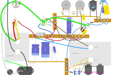
I haven't worked on mine for over a month. I installed the LM334 CCS as described and it worked great without a negative supply. I think I ended up using a 10 or 12K in series with it, and put the LM334 on top of the cathode R, closest to the tube, the R goes to ground. It works great and balances very nicely. You can see my prototype in the picture below. I don't recall making any further distortion tests as I was moving on to another project but I know it sounded nice.
I like the drawing you supplied, is that something you generated? If so what software package is that? It sure makes layout simpler. I haven't scratch built P-P in a long time but really enjoy it. It's not difficult, you just need to be aware of the tube pin numbers, helps to make a diagram indicating them so you don't have to keep getting the magnifier out to see them on the socket 🙄 .
If you can, I would love to see some closeup pics of your PCB and the overall underside as it is wired. Would be interested to know what differences exist. I'll post mine now.
This will be a fun project.
Cheers
PS search my content, I think I had a few other threads related to this amp.
- Home
- Amplifiers
- Tubes / Valves
- Anyone have a Consonance/Opera M99 or M100 integrated amp, I'm starting to mod mine