
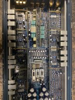
Ok I figured out it was missing a SG2525 chip in U1’s location .
Now off to troubleshoot the amp since it’s stuck in protection mode
Now off to troubleshoot the amp since it’s stuck in protection mode
Amp is in safe mode .
Here is what I get on the SG2525
Pin 1:2.24
Pin 2:2.71
Pin 3:0.00
Pin 4:0.37
Pin 5:2.01
Pin 6:3.83
Pin 7:1.94
Pin 8:0.29
Pin 9:6.31
Pin 10:3.97
Pin 11:0.00
Pin 12:0.00
Pin 13:13.94
Pin 14:0.00
Pin 15:13.94
Pin 16:5.14
Any ideas ?
Here is what I get on the SG2525
Pin 1:2.24
Pin 2:2.71
Pin 3:0.00
Pin 4:0.37
Pin 5:2.01
Pin 6:3.83
Pin 7:1.94
Pin 8:0.29
Pin 9:6.31
Pin 10:3.97
Pin 11:0.00
Pin 12:0.00
Pin 13:13.94
Pin 14:0.00
Pin 15:13.94
Pin 16:5.14
Any ideas ?
Pin 10 is keeping the drive disabled. It needs to be VERY near 0v.
Are the audio driver boards in plug-in headers?
Are the audio driver boards in plug-in headers?
So do you think 1 of the channels is causing the issue ?
Maybe removing the outputs 1 channel at a time to see what channel is causing the issue ?
Maybe removing the outputs 1 channel at a time to see what channel is causing the issue ?
I'd first ,monitor the bridging terminal of each channel with your scope (2ms 5v/div) when you apply power to see if you get a pulse of DC on any channel.
Another option would be to connect a high-power woofer to each channel and listen for a pop or tick when you apply remote.
Another option would be to connect a high-power woofer to each channel and listen for a pop or tick when you apply remote.
The sub channel is causing the issue . I can see it on the scope and also with my meter I can see 20 volts of dc across the speaker terminals on startup
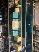
I found the IRF3710’s were defective in the sub channel .
Do I use the 3710 or the 3710Z as replacements?
Do I use the 3710 or the 3710Z as replacements?
I recommend the Z version in 4080 amps. I don't have a suggestion for this amp if it's not a 4080 based amp.
The originals were 3710 in this amp with 47 ohm gate resistors.
Can I try the IRFB4115 and if so do I need to lower the value of the gate resistors ? And if so to what value ?
Can I try the IRFB4115 and if so do I need to lower the value of the gate resistors ? And if so to what value ?
I know nothing about this circuit. There are others who are more familiar with the Audison amps who may have suggestions.
Why not use the originals? They are readily available.
Why not use the originals? They are readily available.
I can use the 3710
But not sure if they are even original since someone has changed the outputs at some point wasn’t original solder
But not sure if they are even original since someone has changed the outputs at some point wasn’t original solder
original mosfets are IRFB52N15D and this amp use 2 stages in BTL to realize the sub channel.
i think the 38n20d are ok!
i think the 38n20d are ok!
Hi,
from what I understand while repairing this amp, this is the story :
originally there was IRFB3710 then IRFB59N10 was used but with this they changed R128-148-210-233 to 1k5 .
Then an upgrade was made by removing C65-C90-D39-D54.
The IRFB4115 is not suitable, unless you modify the R-gate and do some complicated tests and measurements.
The IRFB38N20 seems a bit small to me.
Before changing mosfets, check all driver transistors and open resistors (!)
- Home
- General Interest
- Car Audio
- Audison LRX 600 5 channel amp