I tell you that what could have been a simple repair I have complicated by an oversight, I was repairing a hifonics bxi2610d amplifier which had damaged the source mosfets and some of the audio stage, so as not to make it too long I reached the point of I had an oscillation signal in the 4 banks of the audio stage mosfets, but in one of the banks the only irf9640 got warm , when checking the signal with the scope was a bit strange. The signal was not completly square it has a peak of correct voltage but almost inmediatly, it fall at about 2 volts peak to peak, looked like a continuación of square wave and sawrooth signal.
Last edited:
Checking the oscillation board I found that someone had intentionally cut some jumpers, I repaired these cutted jumpers and when I turned on the amplifier I already had a good square signal in the 4 banks and the mosfet irf9640 no longer got hot, I thought that at that moment, I had repaired it since I injected signal from 40 hz audio and had a clean signal at the output.
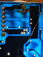
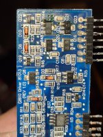
but strangely sometimes when turning on the amplifier, the original failing bank gave a bad oscillation signal again, while checking if any repaired jumper had been false, I accidentally touched the scope ground with the mosfet metal case (drain) after that the Amplifier was in protection, 🙁 when measuring with the oscilloscope in the gates, the amp tries to oscillate, it does not succeed, I know that something was damaged with that short circuit but I'm already lost, I checked the p irf9460 mosfet that was where it touched ground and it is in good condition state, check the PSU signal and mosfets of the source signal and they are working correctly, I have already removed the oscilation board , based on the short l that I am telling you, will you have any suggestions on which component could have been damaged, I already have the board disassembled, in the images you can see the paths i repaired, i think i could posible damage q20,q21,q16 or q23 .
but strangely sometimes when turning on the amplifier, the original failing bank gave a bad oscillation signal again, while checking if any repaired jumper had been false, I accidentally touched the scope ground with the mosfet metal case (drain) after that the Amplifier was in protection, 🙁 when measuring with the oscilloscope in the gates, the amp tries to oscillate, it does not succeed, I know that something was damaged with that short circuit but I'm already lost, I checked the p irf9460 mosfet that was where it touched ground and it is in good condition state, check the PSU signal and mosfets of the source signal and they are working correctly, I have already removed the oscilation board , based on the short l that I am telling you, will you have any suggestions on which component could have been damaged, I already have the board disassembled, in the images you can see the paths i repaired, i think i could posible damage q20,q21,q16 or q23 .
Attachments
Last edited:
I checked again and i detected n channel irf640 damaged, same side of the p channel bank i accidentally shorted with ground 🙁
I Will install a New fet and continúe with testings, i have the board oscillating audio board out of the Maine board, some test to this board before i reinstall it?? Thank you in avance.
I Will install a New fet and continúe with testings, i have the board oscillating audio board out of the Maine board, some test to this board before i reinstall it?? Thank you in avance.
Since the N-channel and P-channel Drains of an output are typically connected together, even a momentary short to Ground of either would likely damage either or both.
What useful test are you thinking of, that can be performed without the 'oscillating board'?😕
What useful test are you thinking of, that can be performed without the 'oscillating board'?😕
Thank you Rick, i was tryng to ask about measuring some specific values of transistors , caps or resistors for this specific oscilation little board, maybe some one tha has reapaired this board model could suggest some specific measures, like q20,q21 etc.
There is something not working correct, in the part that drives one ofvthe irf9640 bank because somethimes when i turn on the amp i get nice square wave in gates, and sometimes i get a semi square signal, with a high peak but falling in aprox 20% of duration of the cycle,
Maybe a false soldier joint a bad transistor that can not hold the loado.
Before my mistake, even with the bad signal in this bank, the amp was running aparently good, but when the signal was not a good square the fet got hot more than the other banks fets.
Maybe a false soldier joint a bad transistor that can not hold the loado.
Before my mistake, even with the bad signal in this bank, the amp was running aparently good, but when the signal was not a good square the fet got hot more than the other banks fets.
Intermittent problems like this are common when the vias are damaged in the main board when the driver board is removed.
Can you duplicate the problem by moving the driver board a bit when it's soldered into the main board?
Can you duplicate the problem by moving the driver board a bit when it's soldered into the main board?
Thank you Perry the board looked like it was never been remoded before, i,m going to make some test of continuity between traces and pins as you suggested.
I have been watching some videos in YouTube from barevids he make some test with thes board inserted but no soldiered,
He only pushes the board to one side making contact wit pins and pin holes,
It seems to work to him, (i have looked at least two videos where he does this) have you tried this method or recomended it. It seems a little Risky, if some pins do not make good contact maybe can damage some other part in the circuit? I think
Thank you again
For demonstration purposes, you could do what he did but it's possible to cause the outputs to fail doing that.
I meant to try it when the driver board was soldered in normally.
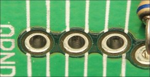
The traces aren't what's likely to be the cause of an intermittent problem. It's the copper vias that are important. You should see perfect tinned cylinders through the full depth of the board.
For your amp, you need to follow the signal back to the driver components on the driver board to see where the signal is deteriorating.
I meant to try it when the driver board was soldered in normally.
The traces aren't what's likely to be the cause of an intermittent problem. It's the copper vias that are important. You should see perfect tinned cylinders through the full depth of the board.
For your amp, you need to follow the signal back to the driver components on the driver board to see where the signal is deteriorating.
Attachments
- Home
- General Interest
- Car Audio
- Bxi2610d mistake