Im still pulling my hairs out trying to get some boards I purchased to give a clean signal out. Last night I had this thought maybe its in my approach.
Im feeding a signal say 1V 1Khz into the input and tracking it thru the circuit.
So far only one board has given me a clean output signal.
My questions.
1. Maybe my mistake i that Im not connecting anything on the output of these boards. Im confused. would putting a load on the output help stabilize the signal.
What kind of load should I put ?. A speaker ? A resistor ? A working amp ? I was using a speaker but then a friend told me you never put a speaker on the output of an opp amp. Or if you do it should be a tiny speaker say from a headphone. What if the design has already taken care of this i.e. it has a 100 ohms resistor on the output.
2. What contributes to the oscillations. Power supply op amps or poor component choices with the op amps.
How to I separate my quest i.e. power related noise vs circuit noise. One way I feel is to find a circuit where there are zero oscillations and use the power from there to drive the circuit that is acting up.
I found a nice circuit on a op-amp tester in Elektor.
In fact last few weeks have been going thru old elektor mags. Looking at their articles on filters, amps, speakers etc.
Found this link you guys may enjoy. Good articles on Frequency filters, op amp testers, various amp and pre amp designs. Some good OG articles by Self.
https://ia600804.us.archive.org/20/items/ElektorMagazine/

A schematic would help.
What sort of circuit is it? Preamp? Phono Preamp? How much gain? Which opamps? Are you getting noise or oscillations? What is the level of noise/osc?
Opamps have fairly high PSRR so unless you are running very gain, a noisy supply should not feed through to the output, unless the supply is horribly noise to begin with.
Opamps oscillate when the output phase shifts 180° and finds a path back to the non-inverting input. Opamps with very high GBW products can exhibit this at a frequency before the open loop gain drops below unity. If you are using them as unity gain buffers, make sure to use opamps that are unity gain stable.
Put a load on the output that the circuit is designed to operate with (not a speaker, not even a small one). Most line level stages are designed to work into 20K or higher. If the load has excess capacitance or long cable length, you may need a series resistance between the opamp output and the load.
We need more/better data than that to answer."some boards" ....
Otherwise it´s just guessing.
Direct link to the boards at least, draw/picture your setup, what do you expect from them, etc.
Run the circuit on batteries to eliminate the supply as a source of noise.
But radiated interference can still be picked up. A load is not usually necessary.
Keep the good circuit as a reference and compare the others to it.
Since you know that this design can work, look for bad connections, wrong or bad parts, etc.
Unless you are highly experienced, such problems are par for the course.
Thanks guys. I have already posted the circuits, the scope traces, the schematics, and all the tests done on other threads. I felt guilty about making this new post as is.
The reason I posted. Was to clarify some doubts.
1. Do I need to load my pre-amp / tone control to settle down the signal. Some have answered yes some have said no. A friend told me to load the output with a 1K to 10K resistor.
2. Is it normal to see a noisy signal on the scope when testing these pre-amp tone control boards based on the NE5532 op amps.
The doubt entered my mind because I just spent the last week speed reading thru the last 30 years of Elektro mags. And in one of the articles. I think it was for a parametric equalizer circuit or a graphics Eq. The said your signal will always look noisy.
Maybe my lack of exp in this field has me looking for a clean signal where there shouldn't be one. Because in spite of the mess I see on my scope screen. The boards do work. And function. Yes the one board which sounds the best is also the one with the cleanest looking signal on the scope.
Right now I am obsessed with a parametric equalizer board. I just purchased. Which has pretty bad oscillations I am in the process of reverse engineering it.
So I can enter it up into proteus or a spice simulator. It has two 500k trim pots that are supposed to shift the freq point for tone and bass.
The bass trim pot sounds best at about 480K and the tone sounds best when set at about 10 ohms.
The PCB has been covered in paint so its hard to extract the info from it. I will keep at this. The unit that just works is nothing more than a Rockola Tone control board with 2 NE opamps. The board that Im trying to fix has 5 NE op amps. With gain, volume, low/mid/high knobs and the trim pots to shift the freq.
Finally I want to build my own proper parametric tone control board where both the Q and the Freq can be varied. If anybody has such a circuit pls share.
1. Do I need to load my pre-amp / tone control to settle down the signal. Some have answered yes some have said no. A friend told me to load the output with a 1K to 10K resistor
The vast majority of the circuits don't care if loaded or not. It is supposed to have sufficient decupling (buffer stage) from the tone network itself to be irrelevant.
2. Is it normal to see a noisy signal on the scope when testing these pre-amp tone control boards based on the NE5532 op amps.
I never used them, but no reason to be noisy. Perhaps the noise is created in the wipers of pots if they are old, too much used, bad quality of the wipers carries a minimum DC current. This last thing must be avoided by proper design.
Where?I have already posted the circuits, the scope traces, the schematics, and all the tests done on other threads.
Direct links?
can´t answer without a schematic.1. Do I need to load my pre-amp / tone control to settle down the signal. Some have answered yes some have said no. A friend told me to load the output with a 1K to 10K resistor.
Define "noisy".2. Is it normal to see a noisy signal on the scope when testing these pre-amp tone control boards based on the NE5532 op amps.
As in mV/uV , dB below signal or a reference level,etc.
FWIW everything above zero degrees Kelvin makes some noise.
The devil is in the details.
Not much use without quantifying it.The doubt entered my mind because I just spent the last week speed reading thru the last 30 years of Elektro mags. And in one of the articles. I think it was for a parametric equalizer circuit or a graphics Eq. The said your signal will always look noisy.
I have been doing more reading.
Testing a headphone amp is easy you load it with resistors 30 ohms to 300 ohms.
Testing an amp is easy. You test it with a 8 ohm or 4 ohm resistor.
Why is there no easy answer for testing a Preamp ?.
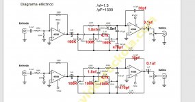
Here are the circuits.
Testing a headphone amp is easy you load it with resistors 30 ohms to 300 ohms.
Testing an amp is easy. You test it with a 8 ohm or 4 ohm resistor.
Why is there no easy answer for testing a Preamp ?.
Here are the circuits.
Attachments
Quantifying Noisy is you send in a clean 1Khz signal. And on the output you dont get a clean wave form. Its either much thicker wave form a kind of ringing. Or a distorted wave form. i.e. its not a clean sine wave you see on the output.
A data base of scope wave forms showing input vs output thru various audio gear would be useful to a lot of people.
A data base of scope wave forms showing input vs output thru various audio gear would be useful to a lot of people.
There is, it's just that preamps and active filters/EQs are normally not sensitive to the load. Peramps shouldn't be at all, and EQs/tone controls shouldn't be either as usually the last filter stage serves also as a buffer... unless it's some special tone control, like ones meant for guitars, which are passive... but otherwise, you should be able to measure them without being loaded... the only way they are sensitive to load is when you overload them (like if you'd short them to 0V "ground" through 4ohm resistor... but you don't need to measure them that way, as that's not the way you are going to be using them... they are supposed to be connected to some high impedance inputs.Testing a headphone amp is easy you load it with resistors 30 ohms to 300 ohms.
Testing an amp is easy. You test it with a 8 ohm or 4 ohm resistor.
Why is there no easy answer for testing a Preamp ?.
Also, if you'd want to load them anyway, then 10K sounds more reasonable than 1K... 1K is bit too low / may be annoying for some opamps in some configurations.
Regarding EQ / tone control schematic recommendations, here's a nice parametric one https://www.gyraf.dk/gy_pd/calreq/calrec.htm
although Q being only a switch... low or high...
Last edited:
Regarding EQ / tone control schematic recommendations, here's a nice parametric one https://www.gyraf.dk/gy_pd/calreq/calrec.htm
although Q being only a switch... low or high...
You read my mind mate. Im doing all this just so that I can learn how to build a Parametric EQ for myself. Variable Q would be nice. But not a must have.
So far Im just learning and collecting ideas for a good parametric EQ.
Its also frustrating that most of the Tone control boards I purchased all seem to suffer from oscillations.
A mate told me there is no way that these boards are selling in the thousands with oscillations and distortion. So I began to question my testing methodology and logic. I would have accepted that all tone control outputs dont look clean. But then I found two systems that do work clean. Somedays I feel like Im chasing my tail. But its all good if one learns something new everyday.
Haywire hookups and cheap power supplies are prone to whistle and squeal.most of the Tone control boards I purchased all seem to suffer from oscillations.
Funny thing is they sound fine i.e. its not like you can hear anything its just that it shows up on the scope as a dirty signal. My plan is to dig up my old fluke scope and chk with that. It could be an issue with my new scope.Haywire hookups and cheap power supplies are prone to whistle and squeal.
Something like a preamp, tone control should work fine without a load. It would not harm unless you go too low. So lets say something like 4.7k as a nice compromise. If your circuit has trouble with that, then it has a design problem.
But having an input "load" would be a good idea. If you leave the input open, then anything that is picked up is also sent through the circuit and comes out the other side. So a resistor at the input of something like 1k is a good idea. Keep that resistor as short as possible, no alligator clip leads.
Then there is the point of hooking up a scope. How and where are you hooking it up? If you are using a long ground lead at the other side of the board then you are picking up noise that isn't really in your circuit. You should use a ground lead as short as possible.
Oscillations are most likely a result of the circuit itself (too much loop gain) or the layout of the pcb or wiring and not the PSU. Noise can be a result of the PSU but with modern components it should not be the case. Batteries can help checking that but even batteries have noise (but likely much less than a switched mode PSU).
Its good practice to insert a 50-100 ohms in series with the output after the feedback takeoff point to isolate any capacitive load.Im still pulling my hairs out trying to get some boards I purchased to give a clean signal out. Last night I had this thought maybe its in my approach.
Im feeding a signal say 1V 1Khz into the input and tracking it thru the circuit.
So far only one board has given me a clean output signal.
My questions.
1. Maybe my mistake i that Im not connecting anything on the output of these boards. Im confused. would putting a load on the output help stabilize the signal.
What kind of load should I put ?. A speaker ? A resistor ? A working amp ? I was using a speaker but then a friend told me you never put a speaker on the output of an opp amp. Or if you do it should be a tiny speaker say from a headphone. What if the design has already taken care of this i.e. it has a 100 ohms resistor on the output.
2. What contributes to the oscillations. Power supply op amps or poor component choices with the op amps.
How to I separate my quest i.e. power related noise vs circuit noise. One way I feel is to find a circuit where there are zero oscillations and use the power from there to drive the circuit that is acting up.
I found a nice circuit on a op-amp tester in Elektor.
In fact last few weeks have been going thru old elektor mags. Looking at their articles on filters, amps, speakers etc.
Found this link you guys may enjoy. Good articles on Frequency filters, op amp testers, various amp and pre amp designs. Some good OG articles by Self.
https://ia600804.us.archive.org/20/items/ElektorMagazine/
- Home
- Source & Line
- Analogue Source
- Question on trouble shooting opamps, pre-amps, and tone control.