Hello,
My usual warning: I am learning. I have much to learn. I will often ask stupid questions and reach incorrect conclusions. Thank you for any education you may give me.
I am trying to learn more about tube amplifier circuits by reading and dissecting examples.
Case in point:

I already peppered this one with questions (A, B, C).
I also assume that only capacitors at 1 and 2 would affect frequency response. Am I correct?
I still have much to learn about picking proper operating points for the tubes themselves. I am not sure if the values shown on this drawing are anywhere near correct. But I suspect they may be odd or wrong. (but it's probably just me and my ignorance)
But in that regards, how can this design be compatible with all of 12AT7, 12AX7 and 12AU7?
Finally, do you know of any reference that would inventory circuit patterns found in tube amplifier designs? I have not been doing this for very long, but I think there are quite a few pieces that appear in many designs and it would be O so wonderful if they were catalogued and explained somewhere.
Again, thank you for any help and sorry for the stupid questions.
My usual warning: I am learning. I have much to learn. I will often ask stupid questions and reach incorrect conclusions. Thank you for any education you may give me.
I am trying to learn more about tube amplifier circuits by reading and dissecting examples.
Case in point:
I already peppered this one with questions (A, B, C).
I also assume that only capacitors at 1 and 2 would affect frequency response. Am I correct?
I still have much to learn about picking proper operating points for the tubes themselves. I am not sure if the values shown on this drawing are anywhere near correct. But I suspect they may be odd or wrong. (but it's probably just me and my ignorance)
But in that regards, how can this design be compatible with all of 12AT7, 12AX7 and 12AU7?
Finally, do you know of any reference that would inventory circuit patterns found in tube amplifier designs? I have not been doing this for very long, but I think there are quite a few pieces that appear in many designs and it would be O so wonderful if they were catalogued and explained somewhere.
Again, thank you for any help and sorry for the stupid questions.

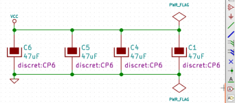
Electrolytic capacitor has a low frequency series resonance. It means, a minimum in its reactace. For frequencies below this, it behaves lile a capacitor as seems obvious. But over this frequency it becomes inductive and its reactance increases. This means that for high frequencies, electrolytic bypass capacitors aren't s bypass. So putting a capacitor whose resonance is much over than the 'lytic enhances high frequency response overlaping their characteristics
Regarding double triodes for the circuit, I suggest the 6DE7 or 6FM7 tubes having an amplifier unit and a power triode in the same bulb. You surely don't want 3 o 4 watts the 6FM7 can give, but its low anode resistance and high gm make them a good choice for cathode follower.
Regarding double triodes for the circuit, I suggest the 6DE7 or 6FM7 tubes having an amplifier unit and a power triode in the same bulb. You surely don't want 3 o 4 watts the 6FM7 can give, but its low anode resistance and high gm make them a good choice for cathode follower.
For example, a 1uF 63V has its resonance in the 100KHz range but a 470uF 25V in the order of some few KHz
The values are about right. A: Correct, this is a headphone amplifier. B: that is a filter capacitor, eliminating feedback through the power rail. All capacitors 1, 2 and the cathode bypass determine the low frequency response. +B1 and +B2 should be around 100...120V.
Some answers here:Again, thank you for any help and sorry for the stupid questions.
http://www.tubebooks.org/Books/intro_Crowhurst_Cooper_1956_High_Fidelity_Circuit_Design-2.pdf
Note that all the electrolytic capacitors on that schematic are drawn with reverse polarity. The rectangle is supposed to be the can (cathode, negative). The line is the positive (anode) terminal.
The cathode bypass capacitor provides a low impedance within the audio band. That maximizes the gain of the input stage.
Tom
The cathode bypass capacitor provides a low impedance within the audio band. That maximizes the gain of the input stage.
Tom
No. As Tom is saying, the cathode cap sets a bass shelf.only capacitors at 1 and 2 would affect frequency response. Am I correct?
https://www.ampbooks.com/mobile/amplifier-calculators/cathode-capacitor/
It is not. As shown it most likelt works reasonable with 12at7.how can this design be compatible with all of 12AT7, 12AX7 and 12AU7?
The 12AT7, 12AX7, and 12AU7 are very similar in only a few characteristics:
Filament Voltage, and filament current
The same pin connections, 1 - 9, to the plate, cathode, grid, and filament.
The 12AT7, 12AX7, and 12AU7 are quite different in these characteristics:
Plate resistance, rp
Transconductance, Gm
Gain, grid to plate, u (mu)
Therefore, they will not perform the same when they are used with the same B+, plate resistors, cathode resistors, etc.
They may all work in your circuit, but not all of them will be utilized to their optimum capability:
Gain, distortion, maximum output signal voltage, etc.
Would you use a 12 cylinder Lamborghini engine to power a Semi Truck Tractor?
Would you use a Semi Truck Tractor engine to power a sports car?
I'd say 100K for the anode and 1.6K for cathode is 12AX7 territory. But without knowing B2 is difficult to be 100% sure.It is not. As shown it most likelt works reasonable with 12at7.
The capacitors are drawn correctly. The 'fat' side is the anode, at least according to modern drawing standard.Note that all the electrolytic capacitors on that schematic are drawn with reverse polarity. The rectangle is supposed to be the can (cathode, negative). The line is the positive (anode) terminal.
Attachments

First, thank you very much for all the help!
And Happy Thanksgiving for those of you who respect that holiday!
I feel privileged to receive this kind of help!
Thank you! I translate this to: Putting film and electrolytic in parallel in the output stage improves high frequency performance by virtue of low-value film capacitors' better handling of high frequencies.
Thank you!
I was trying various values in this Cathode Bypass Capacitor Calculator and was wondering why 50u would not be a better value for the cathode bypass capacitor. (assuming 12AX7)
Thank you, I'll try to find a copy of that book. I am also reading one by Morgan Jones, but it gets quite a bit above my head at this time.
That's what I discovered about the bypass capacitor, indeed. In that schematic, with the values shown, and the calculator I linked to above, I was wondering why 50u wouldn't be a better value for that capacitor.
Thank you! I avoid Lamborghini, semis and tractors entirely. 🙂 But I understand your analogy.
I think that I will give myself the exercise of optimizing this circuit for 12AX7-A, once I have a reasonable understanding of all its part. It'll help me study the process of selecting operating points, etc.
Thank you!
And Happy Thanksgiving for those of you who respect that holiday!
I feel privileged to receive this kind of help!
Electrolytic capacitor has a low frequency series resonance. It means, a minimum in its reactace. For frequencies below this, it behaves lile a capacitor as seems obvious. But over this frequency it becomes inductive and its reactance increases. This means that for high frequencies, electrolytic bypass capacitors aren't s bypass. So putting a capacitor whose resonance is much over than the 'lytic enhances high frequency response overlaping their characteristics
Regarding double triodes for the circuit, I suggest the 6DE7 or 6FM7 tubes having an amplifier unit and a power triode in the same bulb. You surely don't want 3 o 4 watts the 6FM7 can give, but its low anode resistance and high gm make them a good choice for cathode follower.
For example, a 1uF 63V has its resonance in the 100KHz range but a 470uF 25V in the order of some few KHz
Thank you! I translate this to: Putting film and electrolytic in parallel in the output stage improves high frequency performance by virtue of low-value film capacitors' better handling of high frequencies.
The values are about right. A: Correct, this is a headphone amplifier. B: that is a filter capacitor, eliminating feedback through the power rail. All capacitors 1, 2 and the cathode bypass determine the low frequency response. +B1 and +B2 should be around 100...120V.
Thank you!
I was trying various values in this Cathode Bypass Capacitor Calculator and was wondering why 50u would not be a better value for the cathode bypass capacitor. (assuming 12AX7)
Thank you, I'll try to find a copy of that book. I am also reading one by Morgan Jones, but it gets quite a bit above my head at this time.
Note that all the electrolytic capacitors on that schematic are drawn with reverse polarity. The rectangle is supposed to be the can (cathode, negative). The line is the positive (anode) terminal.
The cathode bypass capacitor provides a low impedance within the audio band. That maximizes the gain of the input stage.
Tom
That's what I discovered about the bypass capacitor, indeed. In that schematic, with the values shown, and the calculator I linked to above, I was wondering why 50u wouldn't be a better value for that capacitor.
The 12AT7, 12AX7, and 12AU7 are very similar in only a few characteristics:
Filament Voltage, and filament current
The same pin connections, 1 - 9, to the plate, cathode, grid, and filament.
The 12AT7, 12AX7, and 12AU7 are quite different in these characteristics:
Plate resistance, rp
Transconductance, Gm
Gain, grid to plate, u (mu)
Therefore, they will not perform the same when they are used with the same B+, plate resistors, cathode resistors, etc.
They may all work in your circuit, but not all of them will be utilized to their optimum capability:
Gain, distortion, maximum output signal voltage, etc.
Would you use a 12 cylinder Lamborghini engine to power a Semi Truck Tractor?
Would you use a Semi Truck Tractor engine to power a sports car?
Thank you! I avoid Lamborghini, semis and tractors entirely. 🙂 But I understand your analogy.
I think that I will give myself the exercise of optimizing this circuit for 12AX7-A, once I have a reasonable understanding of all its part. It'll help me study the process of selecting operating points, etc.
I'd say 100K for the anode and 1.6K for cathode is 12AX7 territory. But without knowing B2 is difficult to be 100% sure.
Thank you!
Why not 100uF? Why not 1000uF? What is better...I was wondering why 50u wouldn't be a better value for that capacitor.
I have a couple of follow-up questions:
1. Do the values of 1 and 2 matter from a fidelity standpoint?
What would be the effect of replacing the capacitor at 1 with 1u capacitor? (in my current understanding, the primary role of these coupling capacitors is to prevent high DC to pass on through to the next stage where they would cause problems)
In an actual build of this design, I have seen the electrolytic capacitor at 2 be 150u, which seems to be quite a large value in comparison.
2. This one is very mysterious to me right now. What in this design makes the output impedance of this circuit suitable for headphones, whose input impedance can be lower than 100 ohms.
Why not 100uF? Why not 1000uF? What is better...
Using the calculator I linked to above, I found there is a point of diminishing return at about 50uF. By that I mean that I noticed that increasing the value past that point comes with no further increase in gain.
But that was just me aping it by "playing" with values in the calculator.
Another thing I noticed is that tube circuits are quite flexible when it comes to actual values. Not everything has to be on the dot and sometimes quite a bit of deviation appears to be OK.
The capacitor at "B" bypasses the noise from +B1.
1uF is fine for coupling caps.
Cathode follower with large output caps and high current tube make it suitable for 600 ohm headphones.
1uF is fine for coupling caps.
Cathode follower with large output caps and high current tube make it suitable for 600 ohm headphones.
I can already tell this book is going to be a treasure trove of knowledge. Thank you!
Full PDF of Crowhurst's book here:Thank you, I'll try to find a copy of that book. I am also reading one by Morgan Jones, but it gets quite a bit above my head at this time.
http://www.tubebooks.org/technical_books_online.htm
Direct link:
http://www.tubebooks.org/Books/Atwood/Crowhurst Cooper 1956 High Fidelity Circuit Design.pdf
My bad. They are lacking the + for the polarity marking, though. I'm reminded that my knowledge of European schematic symbols isn't as sharp as it once was.The capacitors are drawn correctly. The 'fat' side is the anode, at least according to modern drawing standard.
I guess we should start using a parallel combination of these for ceramic capacitors with Y5V dielectric... 🙂
Depends on what you're trying to accomplish. The cathode bypass capacitor sets the lower corner frequency for the input stage. If you want that frequency to be lower you use a larger capacitor. Most design for a lower corner around 2-20 Hz.I was trying various values in this Cathode Bypass Capacitor Calculator and was wondering why 50u would not be a better value for the cathode bypass capacitor. (assuming 12AX7)
The audio band is widely accepted to be 20 Hz to 20 kHz, so 20 Hz is the interesting point here. Many want low (or no) impact at 20 Hz, so they place the lower corner frequency "significantly" below 20 Hz. What is "significant" you ask. Well. That depends on whom you ask. If you ask a mathematician, "significantly" probably means a factor of 10^12 to 10^15 away. If you ask a physicist it's probably more like 1000x to 10000x away. And if you ask an engineer, you'll find that a factor of ten away is considered "significantly" greater (or smaller), but a factor of nine is fine. 🙂 That's where the 2 Hz design target comes from. A pole at 2 Hz will result in negligible phase and amplitude difference at 20 Hz.
Some say more is better, so why not 0.2 Hz or 0.02 Hz? My main concern with cutoff frequencies that low is that the circuit will take a while to reach its steady state operating point. With a 0.02 Hz cutoff frequency it'll take a few minutes for the circuit to reach its final operating point. If the anode current in the input tube is running a bit high while the circuit powers up, that will impact the reliability of the input tube.
Tom
- Home
- Amplifiers
- Tubes / Valves
- Learning by dissecting circuits