Hi y'all!
My P.A. drive setup comprises a DEQ2496 and an Ashly protea 3.24CL. I usually patch the DEQ at the output of the board, link the DEQ outputs to the Ashly's inputs, and send the Ashly's outputs to my PA's amps.
I would like to bypass the useless D/A and A\D pair between the DEQ and the Ashly by running a digital link between the two. The DEQ has digital outs, that's easy, but the Ashly has no digital I/O whatsoever... Would anyone be electronically intimate enough with the 3.24 to give me clues and pointers?
I found it's pretty hard to find technical info about the Protea: never ever seen a service manual or schematic anywhere for it.
thanks!
yeah, OK, I'll take some pictures, but not now: I don't have the unit with me at the moment...
And I realised I made a big mistake in my thread title: it's a digital INPUT I want to implement!
And I realised I made a big mistake in my thread title: it's a digital INPUT I want to implement!
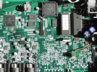
It appears this same circuit board is also used for the model 4.24C, where the one empty input XLR location, and the two empty output XLR locations would be populated. There is place for two DIN-5 jacks, used on th 4.24C for MIDI. No trace of provision for digital I/O unfortunately...
Last edited:
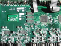
U59's markings are extremely small and hard to read. with the stereo microscope I could see:
CTS5-CB3
12M28800
(dot)04373C3
I suppose it's 12.288 MHz.
for voltage readings I'll have to find an appropriate set of probes so that I don't blow my unit up.
U49,50 and 51 are the dual D/A for the outputs, AKM AK4396
CTS5-CB3
12M28800
(dot)04373C3
I suppose it's 12.288 MHz.
for voltage readings I'll have to find an appropriate set of probes so that I don't blow my unit up.
U49,50 and 51 are the dual D/A for the outputs, AKM AK4396
You will need two SPDIF receivers and two ASRC's. You will need the ASRC for bridging the clock domains.
Thanks for thr reply! I'm a good tinkerer, but I have about zero knowledge in the digital audio inner workings department. I hope you'll forgive my ignorance...
From what I have quickly read, ASRCs are used to convert sample rate. The Protea works at 48KHz, but the DEQ can be configured for different SR, including 48KHz. could I just slave the DEQ to the Protea?
Why two SPDIF receivers? Do you mean one SPDIF receiver and one transmitter?
From what I have quickly read, ASRCs are used to convert sample rate. The Protea works at 48KHz, but the DEQ can be configured for different SR, including 48KHz. could I just slave the DEQ to the Protea?
Why two SPDIF receivers? Do you mean one SPDIF receiver and one transmitter?
You have two 2-channel ADC's hence the need for two SPDIF receivers. The SPDIF datastream has its own clock domain as does the 3.24. The SPDIF receiver also puts out SCLK at 64Fs while the 3.24 expects 128Fs. The ASRC bridges the two.

I see... somewhat!
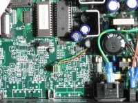
The Protea has three analogue input channels (handled by two, 2-channel A/D chips). In this case I just care for the first A/D chip, as I want to transfer two channels only... I suppose that doesn't matter?...
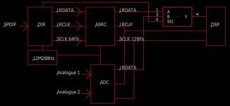
I'd like to understand the diagrams you've drawn... tell me if I'm off.
first block (top left) is the "natural" state of the Preotea?
second block (bottom left) would be first step for digital input to the Protea. Incomplete because SCLK is 64Fs ?
third block would be the complete circuit... ASRC would translate between SPDIF's 64Fs and DSP's 128Fs?
What are those /2 and /256 blocks? Will I have to implement that?
Another consideration I'd have is to be able to keep the analog inputs useable (not simultaneously but switchable). would that be at all possible?
The Protea has three analogue input channels (handled by two, 2-channel A/D chips). In this case I just care for the first A/D chip, as I want to transfer two channels only... I suppose that doesn't matter?...
I'd like to understand the diagrams you've drawn... tell me if I'm off.
first block (top left) is the "natural" state of the Preotea?
second block (bottom left) would be first step for digital input to the Protea. Incomplete because SCLK is 64Fs ?
third block would be the complete circuit... ASRC would translate between SPDIF's 64Fs and DSP's 128Fs?
What are those /2 and /256 blocks? Will I have to implement that?
Another consideration I'd have is to be able to keep the analog inputs useable (not simultaneously but switchable). would that be at all possible?
The ASRC is slaved to the onboard master clock so, data aside, all clocks on the output side of the ASRC are inputs. LRCLK is the sample rate Fs which is the 12M288Hz clock divided by 256. SCLK is 128Fs or master clock divided by 2. The circuit below assumes that the ADC clock signals run all the time so long as the device is powered. The audio/non-audio signal from the DIR is used to switch between analogue and digital. Be aware that the circuit isn't quite the finished article.
Attachments
Well, one thing that's getting clear is that this project is over my head...
I see I'll have to do some studiyng in order to understand better the practice of that discipline.
Any reference to enlightening texts and litterature you can give me?
Thanks immensely rfbrw for taking the time to respond!
I see I'll have to do some studiyng in order to understand better the practice of that discipline.
Any reference to enlightening texts and litterature you can give me?
Thanks immensely rfbrw for taking the time to respond!
There some CD service manuals for players with a digital input that might be of help as well as two related threads. I'll see what I can find and get back to you.
- Home
- Source & Line
- Digital Line Level
- Protea 3.24 digital out hack