Hy,
I will be using mentioned amplifier for a while as a phono preamp, input selector and volume control. Just until I can buy something good.
I am wondering if I can replace 4885 with NE5532 or TL072?
Any other quick mod I can do to it except refreshing some capacitors?
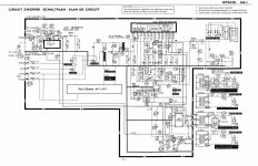
I had attached the schematic, 4558 is at the top left part of it.
Thank you
I will be using mentioned amplifier for a while as a phono preamp, input selector and volume control. Just until I can buy something good.
I am wondering if I can replace 4885 with NE5532 or TL072?
Any other quick mod I can do to it except refreshing some capacitors?
I had attached the schematic, 4558 is at the top left part of it.
Thank you
Attachments
If you think it is not "good", why buy it?
Do you think you will turn something "bad" into something "good" just by rolling Op Amps and leaving everything else exactly the same?
Specially: exact same design.
Change them if you wish, but don´t expect miracles.
Do you think you will turn something "bad" into something "good" just by rolling Op Amps and leaving everything else exactly the same?
Specially: exact same design.
Change them if you wish, but don´t expect miracles.
Maybe I'm missing something but look at the PSU feeding the opamp. Series resistors and no Zeners I can see. If that is correct, then the opamp current draw is critical and anything like a NE5532 would not work.
Is there an error I wonder.
Is there an error I wonder.
Well I don't think it is bad and it was free, but I came across the idea because I have ICs at home and once I had built gain preamp, lpf and bass boost and all three sounded better with NE5532 compared to 4558.If you think it is not "good", why buy it?
Do you think you will turn something "bad" into something "good" just by rolling Op Amps and leaving everything else exactly the same?
Specially: exact same design.
Change them if you wish, but don´t expect miracles.
Last edited:

Wow I didn't even noticed that... Will check when I get home... in that case I could remove resistors and install linear regulators... but I'm not sure if it is worth it.Maybe I'm missing something but look at the PSU feeding the opamp. Series resistors and no Zeners I can see. If that is correct, then the opamp current draw is critical and anything like a NE5532 would not work.
Is there an error I wonder.
Wow, sharp eyes, I hadn´t even noticed it, but yes, it´s common way by cheap makers to save a few cents. (2 Zeners worth)
Sometimes on prototypes or thumb nail sized add-on PCBs where I have very little available space, (or I am using dead bug construction), I use a similar trick: average TL072 or 4558 idle current in normal use is about 3 to 3.5mA, so I keep some 8k2 resistors, given my typical +/-40V supply for my 100W into 4ohm Guitar amps, voltage drop is perfect to get +/-15 or 16V rails for them.
Sometimes on prototypes or thumb nail sized add-on PCBs where I have very little available space, (or I am using dead bug construction), I use a similar trick: average TL072 or 4558 idle current in normal use is about 3 to 3.5mA, so I keep some 8k2 resistors, given my typical +/-40V supply for my 100W into 4ohm Guitar amps, voltage drop is perfect to get +/-15 or 16V rails for them.
So I could use TL072 without psu modifications? Or NE by adding 2 zeners? If so those would be 12v zeners? Where would I need to wire them in?Wow, sharp eyes, I hadn´t even noticed it, but yes, it´s common way by cheap makers to save a few cents. (2 Zeners worth)
Sometimes on prototypes or thumb nail sized add-on PCBs where I have very little available space, (or I am using dead bug construction), I use a similar trick: average TL072 or 4558 idle current in normal use is about 3 to 3.5mA, so I keep some 8k2 resistors, given my typical +/-40V supply for my 100W into 4ohm Guitar amps, voltage drop is perfect to get +/-15 or 16V rails for them.
Ne5532 has more than double the idle current.I'd simply use two 78M18/79M18 regulators for NE5532 instead of the 6.8kohm limiting resistors.Some other small mods would help, but at least it will have better SNR with ne5532. The headroom at the moment is very low although njm4558 is known for its compressing character when approaching hard clipping.C407 would better be 10...47uF.C403 better be 100uF.Maybe I'm missing something but look at the PSU feeding the opamp. Series resistors and no Zeners I can see. If that is correct, then the opamp current draw is critical and anything like a NE5532 would not work.
Is there an error I wonder.
TL072 with no problems, they are very close; NE require more current (about double) so you need lower value resistors.
Pamper the PCB, first find proper dropping resistor and Zener value on a Protoboard,only then transfer those parts to Hitachi PCB
In principle avoid desoldering and resoldering PCB unless forced to do so, it´s easy to burn and damage component pads by that.
Besides, I suspect (if it´s an old amp) that it used brown phenolic paper PCBs, those are very weak.
But even if stronger Epoxy boards, none likes messing with them.
You might want to add IC sockets to facilitate experimenting without repeated soldering.
Small detail:are those DIP8 4558 (2 rows of 4 pins) which are most common all around the World or SIP , straight line 8 or 9 pin? Japanese LOVE them 😉
In that case, you are out of luck, leave as is.
Thankfully it's DIP8...
I have some practice with soldering pcbs old & new, so I'm not affraid of damaging the pads . 🙂
I will go with 78M18 & 79M18, I must check at the store if they have them...
What capacitors should I use on inputs & outputs?
I have some practice with soldering pcbs old & new, so I'm not affraid of damaging the pads . 🙂
I will go with 78M18 & 79M18, I must check at the store if they have them...
What capacitors should I use on inputs & outputs?
Maybe you can change them, if they are DIL style, but what do you expect? The STK Hybrid amps it uses have a very limited quality. They are OK for background music, but avoid using them for serious HIFI. Also keep you whole chain in focus. What phono pickup do you have and what loudspeaker? A single OP-amp does not improve anything if the other components are not of highest quality.
You can be sure SONY used only parts that matched the overall construction.
You can be sure SONY used only parts that matched the overall construction.
So I could use TL072 without psu modifications? Or NE by adding 2 zeners? If so those would be 12v zeners? Where would I need to wire them in?
If you want to fit 5532 or 4562 then you could drop the resistors to 1k 1 watt metal films and fit 12 or 15 volt Zener's across C805 and C806. I think stabilising the rails has to be worthwhile. If you want to use a TL072 then same applies but the resistors can be higher, say 2k2 1watt.
Input cap the same.Output cap...at least 10uF. 47...100u better .Better bipolar (BP or NP)capacitors nichicon muse or panasonic.I will go with 78M18 & 79M18, I must check at the store if they have them...
What capacitors should I use on inputs & outputs?
If they only have 7824/7924 use 330...510 ohms series resistors after the regulators to pins 8 and 4 of ne5532 and 100...220uF decoupling rail capacitors plus one 100nF cap between pin 8 and 4.
After you're done I'll tell you the next step to improve it further. Also buy a small heatsink like the ones used for stepper drivers and some epoxy resin to glue it over the ne5534.That will be a game changer.With higher voltage you improve headroom.Ne5532 can dissipate at least 500mWatts.At +-18v supply 2...300mWatts are to be dissipated which doesn't look like much, but raising the chip temperature it wil perform worse under stress.
Last edited:
Ok don't laugh on my getto setup right now... I had all this laying at home and figured that I would put something together.Maybe you can change them, if they are DIL style, but what do you expect? The STK Hybrid amps it uses have a very limited quality. They are OK for background music, but avoid using them for serious HIFI. Also keep you whole chain in focus. What phono pickup do you have and what loudspeaker? A single OP-amp does not improve anything if the other components are not of highest quality.
You can be sure SONY used only parts that matched the overall construction.
Marantz tt42 turntable (stock Mm cartridge)
Hitachi FA-1 for preamp
Zeck PT7 amplifier (this is PA amplifier, but it sounds really nice)
Pioneer CS-700 speakers (I had seen people talking alot of bad stuff about these, but IMHO they sound good and are still in great shape)
Ok, I`m back from the store... they had 7818 and 7918....
Right now I`m looking at the datasheet and maximum input voltage is 35v...
According to the Hitachi schematic voltages before the resistors are just below that.... I think that I need to use drop down resistors, what value & wattage? I imagine that heatsinks on the regulators will be necessary at that big of a voltage drop right? Can I get away with mounting them on backpanel and isolating the ground?
Thank you for capacitor values @dreamth ...
I actually have some miniature heatsinks with self adhesive that a friend gave me some time ago when he was doing liquid cooled pc build... will use that on NE.
Now a bigger problem & "and I think" the solution at once that will really improve the audio:
I have amplifier connected via headphone output from the Hitachi...
I had studied the schematic and I see that STK is powering my output... they just took the speaker output and used 300ohm resistor in series for headphone output...
I have the preamp that @Mooly designed for me in 2017 ... wow time flies so fast... I need the gain because Zeck amplifier uses +4dBu line level... I attached the schematic. Its a single rail design with 4558 / TL072 / NE5532 IC....
I can either grap positive rail after the regulator to power this one or I can build dual rail version... but I don`t see a reason, this one is already made and it sounds good....
Can I hijack the signal from L, R input pins of the STK and leave the STK connected as is?
Attachments
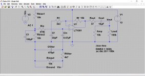
You can use it single rail, but you'll head into headroom limitation on dusty records with its voltage supply cause now you have 4x gain attached to the previous phono preamp gain whatever that may be.
If you do it , then you'll remove all the bias network of your preamp, go dual rail as well with that preamp and link the PIN 1 input of the STK chip to the input of your preamp.You'll remove stk4141 entirely from your amp and accomodate Molly's preamp inside with that new +-18v supply,
OR
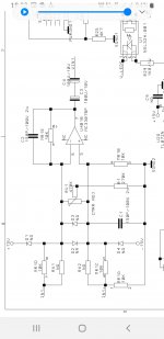
You can open the Zeck amp and place 4 more resistors of 10k ohms each in place of NC resistors: RX1, RX201 and RX2, RX202
That IC inside the zeck amp has +-15v supply so less headroom than your phono preamp, but at least has input clamping diodes.
Thus you won't need to use or modify Molly's amp.
Phono preamps are really difficult to tackle properly when you want the best sound of the whole audio chain.
If you do it , then you'll remove all the bias network of your preamp, go dual rail as well with that preamp and link the PIN 1 input of the STK chip to the input of your preamp.You'll remove stk4141 entirely from your amp and accomodate Molly's preamp inside with that new +-18v supply,
OR
You can open the Zeck amp and place 4 more resistors of 10k ohms each in place of NC resistors: RX1, RX201 and RX2, RX202
That IC inside the zeck amp has +-15v supply so less headroom than your phono preamp, but at least has input clamping diodes.
Thus you won't need to use or modify Molly's amp.
Phono preamps are really difficult to tackle properly when you want the best sound of the whole audio chain.
Attachments
Last edited:
Now that is something. I never tought of modifying the Zeck... I always needed some sort of preamp with it, I will go that route....You can use it single rail, but you'll head into headroom limitation on dusty records with its voltage supply cause now you have 4x gain attached to the previous phono preamp gain whatever that may be.
If you do it , then you'll remove all the bias network of your preamp, go dual rail as well with that preamp and link the PIN 1 input of the STK chip to the input of your preamp.You'll remove stk4141 entirely from your amp and accomodate Molly's preamp inside with that new +-18v supply,
OR
You can open the Zeck amp and place 4 more resistors of 10k ohms each in place of NC resistors: RX1, RX201 and RX2, RX202
That IC inside the zeck amp has +-15v supply so less headroom than your phono preamp, but at least has input clamping diodes.
Thus you won't need to use or modify Molly's amp.
Phono preamps are really difficult to tackle properly when you want the best sound of the whole audio chain.
Thank you for explanation... yes mine is PT7 and there is also PT9... I hope it will have enough gain after the modification...It is modifyable by design because it needs to allow higher and higher powers with the successive models, thus higher input gains too and you don't have the highest power model so its gain is kept low by using only 10kohm input resistors .
I need about 12db of gain.
You can play with those resistors around the op amp until you get the right gain and impedances for you: https://www.electronics-tutorials.ws/opamp/opamp_5.html
- Home
- Amplifiers
- Chip Amps
- Hitachi HA-1, can I replace 4558?