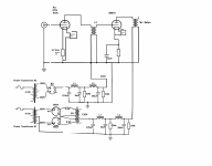
I need some help with the 866a rectifiers. My schematic is below. Here are some measurements.
HV Tx AC = 120Vac
Filament Tx AC = 120Vac
5Vac Filaments. Looks good.
Point A to Ground = 0Vdc
So, I know something is wrong because A to Gnd should be about 800Vdc, correct? Also, there is no blue light within the 866A. Filament is glowing orange, but no blue/purple glow.
So, I then used my voltmeter and touched the (+) probe to BC1 (bayonet 1) and the (-) probe to Gnd. This measured 800V and then the voltage slowly starts to decline. What is interesting is that when the probe is on BC1, the blue/purple glow appears in BC2. Yes, BC2. So, then I tried the opposite. Touched probe to BC2 (and Gnd) and then BC1 started to glow blue/purple.
I am completely confused at this point. Thoughts?
I would CAREFULLY put a properly rated load on your ps output. Beware of the max current and heat dissipation of your dummy load. Then check your voltages. Remember to give your MV’s a minute or two of warm up time to stabilize before your test.
Are you preheating mercury vapour rectifiers, before HT (AC) voltage connected to 866 tubes?
For unused tubes minimum 30 min. required.
If it was unused some days, 15-20 min. preheating necessary. After it, in each day the preheating period is 10-15 min.

Which type filament transformer used?
For unused tubes minimum 30 min. required.
If it was unused some days, 15-20 min. preheating necessary. After it, in each day the preheating period is 10-15 min.
Which type filament transformer used?
Last edited:
Good to see you Pat!
There is no load on your PSU. The amount of expected blue glow will depend of the current drawn through the rectifier. Make sure your capacitors will withstand the 800V x 1.41 unloaded circuit.
There is no load on your PSU. The amount of expected blue glow will depend of the current drawn through the rectifier. Make sure your capacitors will withstand the 800V x 1.41 unloaded circuit.
Bela - Once I received the tubes, I preheated the tubes for several hours. Then, each time I turn them on, I pre-heat them for 2-5 minutes. Based upon the graph you included, I will start pre-heating for 10 minutes. I am using a custom filament transformer from Monolith. The transformer supplies AC voltage for all my tubes in the amp, each with a dedicated filament winding. For the 866A, the winding is 2.5 - 0 - 2.5, 5A.
50AE - My caps are 1K rated, so too small for the 800V ???
I still can't figure out why there is no load.
50AE - My caps are 1K rated, so too small for the 800V ???
I still can't figure out why there is no load.
You have no equivalent load on your power supply schematic. Are you relying on your signal power stage biasing to draw the current,?
The mentioned 5K primary OPT are your primary reflected load and represent an AC loadline to your power stage, but they're not your representive DC power supply load.
As for the 1kV rating, yes, it's too small to withstand unloaded choke input ramping voltage. You need to have some kind of clamping protection when the power supply is unloaded.
1. I hope the filament winding is rated for at least 5 Amps continuous. Otherwise, it is smoking.
And, the start-up filament current is many times more than 5 Amps (cold filament wire).
2. 800Vrms x 1.4 = 1120V.
And, there are Only two 330k Resistors "loading" the B+ Primary and the rectifiers. When unloaded, it probably is closer to 850Vrms or 900Vrms than to 800Vrms.
All B+ capacitors should be rated at 1500VDC or more.
A. what if the output tubes are not warmed up?
B. what if there is a Transient on the 120VAC power line?
Do not try and cheat Mother Nature (or God either).
"Cheap is not good and Good is not cheap" (author Frank Reps in "Sound Practices", 2A3 "Baby Ongaku", designed by Gordon Rankin).
3. High Voltage B+ . . . ? Wow!
Use some Real Serious bleeder resistors. They should draw lots more current than parallel 330k Ohms, and should be rated for lots of watts.
Otherwise, you will be 6 feet under before the capacitors discharge.
Safety First!
"Prevent the Surviving Spouse Syndrome".
280 uF x 165,000 Ohms = 41.25 Seconds for One Time Constant. The voltage after 1 time constant is 36.3% of the original voltage.
1100V x 0.363 = 399.7VDC after 1 time constant (41 Seconds)
41 seconds later, you still have 399V after you turn the B+ off. The only load is two 330k resistors.
Any good B+ power amplifier power supply has enough extra power to use much lower resistance bleeder resistors. If not, get a better power supply.
A 25k 100Watt power resistor will discharge the total capacitance of 280uF on an 1100VDC B+ supply, to 399V in 7 seconds.
Give it another 7 seconds (399V x 0.363 = 144.8V). 144.8V after 14 seconds.
Last edited:
In my all -permanent tentative 🙂- DHT amp (841, 10Y/FET CF, 801a PSE) all (R.C.) filament powered up with HT PSU MV (AX50) rectifiers filament.
The HT transformer secondary CT trap connecting via manual switch to "ground" (after few.. ten minutes), so when it powering up the MV rectifiers and the load (power tubes) are conducting immediately, so MV rectifiers load is available.
The HT transformer secondary CT trap connecting via manual switch to "ground" (after few.. ten minutes), so when it powering up the MV rectifiers and the load (power tubes) are conducting immediately, so MV rectifiers load is available.
Oh,
Does Power Supply Simulation Software include a feature that tells you how long it takes a power supply to discharge (with no load other than bleeder resistors).
Specifically to discharge to 42VDC?
If the software can not tell you that, it is subject to "The Surviving Spouse Lawsuit".
(who can tell me where the 42VDC figure came from?)
6A3sUMMER - I was reading where a good rule of thumb for bleeder resisters and loading the first choke = 1Kohm for each Henry of L1. So, I have a 12H L1 = 12K ohm bleeder. Sound right?
Using your calculations, 280uF x 12,000 = 3.3 seconds
Do you recommend putting the bleeders after each cap in the cLCLC power supply?
Using your calculations, 280uF x 12,000 = 3.3 seconds
Do you recommend putting the bleeders after each cap in the cLCLC power supply?
"Surviving Spouse Syndrome" is overrated. Many spouses would celebrate! 😛
Also, wasting that much power in a bleed resistor is just ridiculous. Maybe if you switch in a resistor on power loss? Not sure how many relays want to work with your voltages though. I know, use a 1700V depletion MOSFET as the switch.
Also, wasting that much power in a bleed resistor is just ridiculous. Maybe if you switch in a resistor on power loss? Not sure how many relays want to work with your voltages though. I know, use a 1700V depletion MOSFET as the switch.
banpuku,
The rule you read is probably primarily aimed at Choke Input filters, to keep the B+ from rising too high, when there is very little load.
An example would be a high power amateur radio CW transmitter. The key goes down, lots of current on the B+. The key comes up, only bleeder current on the B+.
Where to put bleeder resistors has tradeoffs.
Your power supply filter is (relatively small first c), choke, c, choke, c.
I would call this a modified choke input filter, because the input cap is very low capacitance, and the choke is 12 Henry, certainly enough inductance to meet the critical inductance rule for a medium to large current draw from the amplifier output tube(s).
As long as all solder connections, and all choke wires are good, the bleeder can be across any capacitor.
But, if you put it at the far end, and closer to the rectifier a choke opens up, or closer to the rectifier a solder connection opens up, the first capacitors will stay charged, nothing connected to bleed down.
12K will draw (dissipate) 100 Watts from an 1100V B+. That is like a 100 Watt incandescent light bulb (heat). They are made to operate in the open.
I generally pick resistors that are rated 3x to 5x the power that they will dissipate in my amplifier.
Suppose you use 3 bleeder resistors, each one is 36k Ohms, each one with a 100 Watt rating. Each resistor will dissipate 33 Watts, not too bad.
Connect them across 3 of your different capacitors (at least 3 caps will discharge, even if a choke wire breaks).
Your 12k (or 3 each 36k) are drawing a total of 92mA. If that is too much, then consider the following:
3 each 50k, 50 Watt resistors, 16,700 Ohms. 1100V, 66mA total bleeder current. 24 Watts dissipated in each resistor.
if you have lots of holes in the amplifier bottom plate, and lots of holes in the amplifier top plate, you get enough ventilation to be able to use 50 Watt rating on each 50k (as long as they are well spaced from anything else. Otherwise use 100 Watt dissipation rated 50k resistors.
The 16,700 Ohm x 280uF time constant is 4.7 seconds, Less than 10 seconds for 2 time constants.
Turn the amplifier off, and disconnect the power cord.
I bet it takes you more than 10 seconds to take out all the screws and remove the bottom panel from the amplifier.
Do you see how this works?
Last edited:

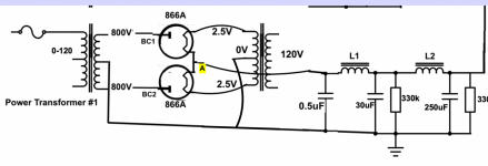
Thanks everyone for the input. Here is my full schematic. While I am learning quite a bit about bleeder resistors, I am still facing the problem of the 0V B+. Apparently from no load??? PLEASE provide your input on anything to modify or test to help with the 0V B+ issue. I am at a loss here.
Attachments
Disconnect the CT from the middle of the tube filaments and see if that makes a difference, make "A" the CT of the heater xfmr.

Tom - I did confirm that there is 800V coming from the power transformer to the bayonet caps.
Kodabmx -I just tried that and it did not help. It did cause the filaments in the 866A to glow brighter. AND, when I put the multimeter probes between a bayonet cap and ground, BOTH 866A tubes started to glow blue/purple. But in the end, still the same problem. I still can't put my finger on it. 50AE is suggesting that my power supply is not biased and therefore not drawing current. How do I get bias on the power supply?
Kodabmx -I just tried that and it did not help. It did cause the filaments in the 866A to glow brighter. AND, when I put the multimeter probes between a bayonet cap and ground, BOTH 866A tubes started to glow blue/purple. But in the end, still the same problem. I still can't put my finger on it. 50AE is suggesting that my power supply is not biased and therefore not drawing current. How do I get bias on the power supply?
- Home
- Amplifiers
- Tubes / Valves
- 866A rectifier: help needed