Hi Folks,
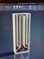
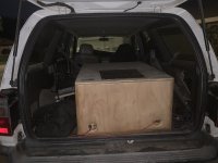
I think this might be my first post here, so please go easy. I recently completed a Martinnson ROAR12 build using a Beyma 112nd/w. It simulated quite nicely in Hornresp

The build was easy enough, but the results were somewhat interesting. The intended use is a small PA for my farm and as the bottom end of a bass guitar rig.
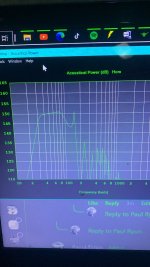
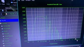
I am fortunate enough to be able to measure in a paddock 100+m from anything reflective. The results are as follows (uncorrected SPL) -

The efficiency is simply ridiculous at 100hz, but the low end is rather disappointing. 45hz is some 15db down on 100hz. It still outputs a surprising amount of noise at 45hz, and a simply ridiculous amount of noise at 100-150hz. The 1w/1w efficiency at 100hz works out around 110db and if I eq this out, the woofer seems to run out of excursion down low.
I have read some threads where the merits of the ROAR design were questioned, but not resolved.
Has anyone built one of these and has similar results? Is there a likelihood I have stuffed up something in the construction, or is it more likely that those questioning the design and simulations were correct?
Any input would be appreciated.
Lax
I think this might be my first post here, so please go easy. I recently completed a Martinnson ROAR12 build using a Beyma 112nd/w. It simulated quite nicely in Hornresp
The build was easy enough, but the results were somewhat interesting. The intended use is a small PA for my farm and as the bottom end of a bass guitar rig.
I am fortunate enough to be able to measure in a paddock 100+m from anything reflective. The results are as follows (uncorrected SPL) -
The efficiency is simply ridiculous at 100hz, but the low end is rather disappointing. 45hz is some 15db down on 100hz. It still outputs a surprising amount of noise at 45hz, and a simply ridiculous amount of noise at 100-150hz. The 1w/1w efficiency at 100hz works out around 110db and if I eq this out, the woofer seems to run out of excursion down low.
I have read some threads where the merits of the ROAR design were questioned, but not resolved.
Has anyone built one of these and has similar results? Is there a likelihood I have stuffed up something in the construction, or is it more likely that those questioning the design and simulations were correct?
Any input would be appreciated.
Lax
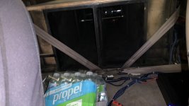
The measurement indicates that you have an air-leak somewhere around the driver.
I have built a ROAR12 with a B&C 12PS100, and I am very happy with the performance. It exceeded all my expectations.
I have built a ROAR12 with a B&C 12PS100, and I am very happy with the performance. It exceeded all my expectations.

Thanks Circlomanen. When you say around the driver, do you mean in the box in the vicinity of the driver, or around the actual driver itself? Around the driver itself is easily fixed with some silicone, but a leak in the internals of the box, not so simple at all!The measurement indicates that you have an air-leak somewhere around the driver.
I have built a ROAR12 with a B&C 12PS100, and I am very happy with the performance. It exceeded all my expectations.
Last edited:
It’s not new driver. I’m not using t nuts (they weren’t available where I live when I bought them. I’m using hex head wood screws through a double thick baffle.Is it a new driver or has it been used for a while now? If you're using t-nuts and bolts to secure the driver, silicone should not be needed and I look at it as a very last resort.
Two different approaches… lows exist in both, but they REALLY (seem /perceived as ) show up (with much less output) on the rendering and on the right design which has a flat response that doesn’t bias the output and confuse it as all upper freq in the subwoofers loudness?
Attachments


Last edited:
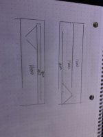
I dunno, but ‘lows‘. Are always an issue … but if it inst a leak, then it’s interesting and maybe I’ll test mine again(I have no interest in breaking another laptop out in the country in a car, however😆lows?, and not…? It’s subjective? (the picture above on the left doesn’t help. I didn’t realize it was the wrong one. (my roar isn’t typical it seems ?))
Attachments
Maybe baffle step? the peak and dip seem pretty the same freq, only with a linear attenuation towards low end...
Are you suggesting that the response could indeed be closer to linear, but baffle step is causing the measured results? I'm a bit of a rookie here, so any advice is appreciated.Maybe baffle step? the peak and dip seem pretty the same freq, only with a linear attenuation towards low end...
I'm an Ultra rookie then! I'm saying that the sim showed a local peak arround 50 Hz and a dip at arround 60 Hz, and the same seems to be true for ur meassurment. Only now that i see it in more detail its about 5 Hz shifted towards low freq. I dunno what that last thing may suggest. But what i was saying was that the dips and peaks seem correlated, but it seems to be like a linear attenuation (this is not the appropiate term), some sort of linear (i mean a line, lets say -10dB/oct supperimposed to the expected response) roll off in the low end. If u look at a baffle step curve, i'm guessing it could be that what we are seeing here.
I found interesting (and thats why i liked the comment) what circlomamanen said about the air leak arround the driver, as i dunno what that would create. But seems reasonable that an interference between rear and front wave would have such an effect. Also box compilance that driver "sees" would change dramatically in such case. I would love to know why he states that, but i believe him, as he was pretty categoric and straight to the point.
Edit: Either case, i would check how well the driver is attached to front baffle, make sure its airtight (use silicone or something like that, beware of gases as it cures). If the design has a flushed mounted woofer, i would make sure the driver adjusts as best as possible. Re meassure, if that didnt do the trick, round the edges of the front baffle. If that didnt do it, find a comprommise, dsp, eq, positioning, etc.
Ok, i saw the design now, i really dont know how that thing works! lol
Last edited:
i have read people made a rubber round gasket and, sadwich it between driver and baffle, so you remove the driver and stick it with those glue sticks so it dont move whem screw the driver back in. that fixed a lot of issues of air leak at the driver. hope you dont have an inside panel that leaks. good luck.
Max.
Max.
Run an impedance curve check on your build. It's the best way to confirm if what you built matches what you sim'd in Hornresp. In particular, confirm that the dips in the measured impedance curve match the dips predicted in Hornresp.
use gasket tape to seal the driver. Usually the drivers are supplied with a front gasket fitted though?
The REW manual shows how to construct a very simple impedance measurement jig.
you can check for leaks perhaps with a very bright light ?
The REW manual shows how to construct a very simple impedance measurement jig.
you can check for leaks perhaps with a very bright light ?
use gasket tape to seal the driver. Usually the drivers are supplied with a front gasket fitted though?
The REW manual shows how to construct a very simple impedance measurement jig.
you can check for leaks perhaps with a very bright light ?
I did do an impedance sweep with my DATS V3, but paid little attention beyond seeing the 4 peaks that the hornresp simulation showed. I’m travelling for work at present, so I will post a picture of the sweep towards the end of the week.Run an impedance curve check on your build. It's the best way to confirm if what you built matches what you sim'd in Hornresp. In particular, confirm that the dips in the measured impedance curve match the dips predicted in Hornresp.
I do recall that all 4 peaks were roughly the same magnitude, which I’m pretty sure the simulation didn’t show.
The height of the peaks could be affected by a number of factors, including driver parameters not taken into consideration in the Hornresp sim.I do recall that all 4 peaks were roughly the same magnitude, which I’m pretty sure the simulation didn’t show.
What's important is that the dips in the response (1) occur at the frequencies indicated in the sim, and (2) reach minimum impedance values that are very close to those predicted in the sim.
The height of the peaks could be affected by a number of factors, including driver parameters not taken into consideration in the Hornresp sim.
What's important is that the dips in the response (1) occur at the frequencies indicated in the sim, and (2) reach minimum impedance values that are very close to those predicted in the sim.
Attachments
Hi Folks,
The box definitely does not have any external leaks and there is no leaking around the driver (a small bead of silicone has been place around it for good measure..
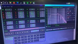
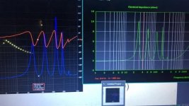
Below are the Hornresp impedance simulation and the DATS measures impedance. Can anyone tell my by looking at these where my problem may lie?
I can hear a slight rattling inside the box at low volumes and very low frequencies but have been unable to isolate it. It may well be the speaker itself. Peaks seem to be approximately in the same place, but certainly not of the same magnitude. I have no idea what to make of this, so any help would be appreciated. I really want to make this box work, but am losing hope. If I can get it to be as load at 50hz as it is at 100hz is will be perfect for my needs.
Thanking you all!


The box definitely does not have any external leaks and there is no leaking around the driver (a small bead of silicone has been place around it for good measure..
Below are the Hornresp impedance simulation and the DATS measures impedance. Can anyone tell my by looking at these where my problem may lie?
I can hear a slight rattling inside the box at low volumes and very low frequencies but have been unable to isolate it. It may well be the speaker itself. Peaks seem to be approximately in the same place, but certainly not of the same magnitude. I have no idea what to make of this, so any help would be appreciated. I really want to make this box work, but am losing hope. If I can get it to be as load at 50hz as it is at 100hz is will be perfect for my needs.
Thanking you all!
Additionally, I am certain my measurements (mic in the horn mouth) are correct. There is an absolute audible drop that coincides with the REW measurements.
- Home
- Loudspeakers
- Subwoofers
- ROAR 12 -Disappointing Results